
In the realm of software engineering, the gap between business requirements and technical implementation is often bridged by visual modeling. A Use Case Diagram is one of the most effective tools for this bridge. It provides a high-level view of how different users (actors) interact with a system to achieve specific goals. This tutorial breaks down the architecture of an Online Shopping System, focusing on the precise syntax required in modeling tools like VPasCode and PlantUML to ensure your diagrams are not just pictures, but executable specifications.
Understanding the Architecture: Actors and Boundaries
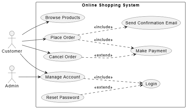
Every system diagram begins by defining the system boundary and the external entities that interact with it. In the provided model, we are visualizing an Online Shopping System.
First, we identify the Actors. These are the external roles that interact with the system:
- Customer: The primary user who browses products, places orders, manages their account, and can cancel orders.
- Admin: A specialized role, likely a system administrator, who primarily manages user accounts.
The System Boundary is represented by a rectangle labeled “Online Shopping System.” Everything inside this box represents functionality internal to the software, while everything outside represents external agents.
Mastering Relationship Syntax: Include vs. Extend
The core complexity of Use Case modeling lies in defining how use cases relate to one another. PlantUML and similar tools require strict syntax to distinguish between mandatory behaviors and optional extensions.
1. The Include Relationship (Mandatory)
The <<include>> relationship indicates that the behavior of the included use case is mandatory whenever the base use case is executed. It is a way to reuse common behavior.
In our diagram:
- Place Order includes Make Payment and Send Confirmation Email. You cannot place an order without paying and receiving confirmation.
- Manage Account includes Login. You must log in to manage your account.
Crucial Syntax Note: In the corrected PlantUML code provided in the context, the syntax UC2 ..> UC3 : <<include>> is used. The double dots (..) create a dashed line, which is the standard notation for dependency and inclusion relationships in UML. The arrow points from the base use case to the included use case.
2. The Extend Relationship (Optional)
The <<extend>> relationship indicates that the behavior of the extending use case is optional and only occurs under specific conditions. It allows for modeling exceptions or “happy paths” that might not happen every time.
In our diagram:
- Reset Password extends Login. This happens only if the user forgets their password.
- Cancel Order extends Make Payment. This is a specific conditional scenario where a cancellation triggers a payment reversal or refund logic.
Syntax Rule: The arrow for <<extend>> points from the extending use case to the base use case. For example, the arrow goes from Reset Password to Login, not the other way around.
Translating Logic to Code: The PlantUML Blueprint
Visual modeling tools often allow you to write code to generate diagrams. This approach is superior to drag-and-drop tools for version control because the diagram is stored as text. Below is the breakdown of the specific code structure required to generate the diagram shown.
@startuml
' Use Case Diagram for Online Shopping System

left to right direction
' Gives a horizontal layout

' Define actors
actor "Customer" as customer
actor "Admin" as admin

' Define system boundary
rectangle "Online Shopping System" {
  ' Primary use cases
  usecase "Browse Products" as UC1
  usecase "Place Order" as UC2
  usecase "Make Payment" as UC3
  usecase "Cancel Order" as UC4
  usecase "Manage Account" as UC5

  ' Secondary use cases for relationships
  usecase "Login" as SUC1
  usecase "Reset Password" as SUC2
  usecase "Send Confirmation Email" as SUC3
}

' Actor associations (Solid lines)
customer --> UC1
customer --> UC2
customer --> UC4
customer --> UC5
admin --> UC5

' Include relationships (Mandatory)
' Dashed arrow with <> stereotype
' "Place Order" always includes "Make Payment" and "Send Confirmation Email"
UC2 ..> UC3 : <>
UC2 ..> SUC3 : <>

' "Manage Account" always requires "Login"
UC5 ..> SUC1 : <>

' Extend relationships (Optional)
' Dashed arrow with <> stereotype
' "Reset Password" is an optional extension of "Login"
SUC2 ..> SUC1 : <>

' "Cancel Order" may optionally involve a refund via "Make Payment" logic
UC4 ..> UC3 : <>

@enduml
This code snippet demonstrates the robustness of text-based modeling. By using <<include>> and <<extend>> stereotypes, we explicitly define the nature of the dependency, ensuring that anyone reading the diagram understands the mandatory vs. optional nature of the business processes.
Conclusion: From Blueprint to Code
Use case descriptions and diagrams are more than just documentation; they are a communication tool that ensures clarity, reduces rework, and aligns technical teams with business goals. By combining the visual clarity of use case diagrams with the detailed narrative of use case descriptions—complete with preconditions, happy paths, alternatives, and exceptions—product managers and analysts can create a robust blueprint for development.
Whether you are defining a simple login feature or a complex multi-step checkout process, adhering to a structured format ensures that no scenario is left to chance. Leveraging tools like PlantUML further enhances this process by keeping your visual models synchronized with your textual specifications, ultimately leading to higher-quality software and happier stakeholders.