Understanding the static structure of a system is a foundational skill for any software architect or system designer. While class diagrams provide the blueprint, object diagrams offer a snapshot of the actual instances existing at a specific moment in time. This guide delves into the mechanics, syntax, and practical application of UML object diagrams. We will explore how these diagrams function within the broader Unified Modeling Language ecosystem and why they remain relevant for modern system analysis.
What Exactly is an Object Diagram? 🧩
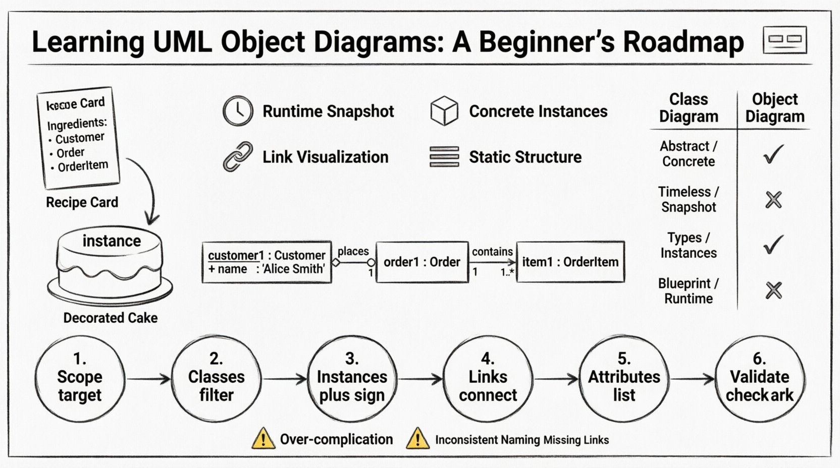
An object diagram represents a specific instance of a system’s structure. Think of a class diagram as a recipe, and an object diagram as the actual cake baked from that recipe. In the Unified Modeling Language (UML), object diagrams are categorized as instance diagrams. They depict objects, which are instances of classes, and the links that exist between them at a particular point in time.
Unlike class diagrams that define the potential structure, object diagrams describe a concrete state. This distinction is vital for developers and stakeholders who need to visualize data flow, memory allocation, or runtime relationships. By focusing on instances rather than definitions, these diagrams clarify how data interacts in real-world scenarios.
Key Characteristics
- Static Structure: Like class diagrams, object diagrams represent static structure, not behavior or state transitions.
- Runtime Snapshot: They capture the system state at a specific moment.
- Concrete Instances: Every box represents a specific object with a unique identity.
- Link Visualization: They show how objects are connected via associations.
Core Components and Syntax 🎨
Building an object diagram requires adherence to specific notation rules. These rules ensure that anyone reading the diagram understands the relationship between the instances. The syntax is derived directly from the class diagram but applied to concrete data.
1. Object Notation
Objects are depicted as rectangles. Unlike classes, which are usually bolded, object names often include a colon separator. This separator divides the instance name from the class type. The standard format is:
objectName : ClassName
For example, customer1 : Customer indicates an instance named customer1 belonging to the Customer class. The instance name is often underlined to emphasize its uniqueness, though this is not strictly mandatory in all notation styles. However, using an underline helps distinguish it clearly from the class name.
2. Link Notation
Links are the lines connecting objects. They represent associations between instances. The visual representation of a link mirrors the association line in a class diagram. However, the ends of the link may display role names and multiplicity constraints.
- Association Lines: Solid lines connecting two objects.
- Role Names: Labels indicating the role an object plays in the relationship (e.g., owner, buyer).
- Multiplicity: Numbers or ranges (e.g., 1, 0..*, 1..1) at the ends of the link indicating how many instances can participate.
3. Aggregation and Composition
Part-whole relationships are also represented. Aggregation is shown as a hollow diamond, while composition uses a filled diamond. These diamonds sit on the side of the “whole” object, pointing toward the “part” object. This visual cue is crucial for understanding ownership and lifecycle dependency.
Understanding Instances and Naming Conventions 📝
Naming instances correctly is a common stumbling block for beginners. The naming convention serves two purposes: identification and clarity. A well-named instance tells you what the object represents without needing to check the class definition repeatedly.
Instance Naming Rules
- Uniqueness: Within the scope of the diagram, an instance name must be unique. You cannot have two objects named
order1in the same diagram. - LowerCamelCase: Instance names typically use lowercase starting letters (e.g.,
invoice1), while class names use UpperCamelCase (e.g.,Invoice). - Descriptive vs. Generic: While
order1is acceptable,pendingOrder1might be more descriptive if the state matters. However, object diagrams usually focus on structure, not state attributes, so generic names are often preferred for simplicity.
Attribute Display
One of the unique features of object diagrams is the ability to show attribute values. While class diagrams show attribute types, object diagrams can show attribute values. This is done by listing the attributes inside the object rectangle, below the instance name and class type.
| Component | Class Diagram | Object Diagram |
|---|---|---|
| Instance Name | Customer |
customer1 : Customer |
| Attributes | + name : String |
+ name : "Alice Smith" |
| Links | Association Lines | Link Lines |
| Scope | Blueprint / Type | Runtime / Instance |
Notice how the attribute value is quoted to indicate a string literal. This level of detail helps stakeholders verify if the data structure aligns with expected business logic.
Relationships and Multiplicity in Detail 🔗
The power of an object diagram lies in how it visualizes relationships. In a class diagram, multiplicity defines the rules. In an object diagram, the actual connections demonstrate compliance with those rules. Understanding how to draw these links is essential for accurate modeling.
Association Links
Associations represent a structural relationship. For example, a Customer object is associated with an Order object. In the object diagram, you draw a line between customer1 and order1. You must ensure that the link exists logically. If the class diagram defines a one-to-many relationship, the object diagram should reflect that at least one Customer is linked to one or more Order instances.
Multiplicity Constraints
Multiplicity constraints are often displayed near the link ends. Common constraints include:
- 0..1: The object may or may not be linked.
- 1..1: The object must have exactly one link.
- 0..*: The object can have zero or many links.
- 1..*: The object must have one or many links.
When modeling, ensure that the number of links drawn matches the constraints defined in the underlying class structure. If a class diagram says a BankAccount must have a Customer (1..1), your object diagram cannot show a BankAccount object with no links to a customer.
Object Diagram vs. Class Diagram 🆚
Confusion often arises between object diagrams and class diagrams. While they share similar visual languages, their purposes are distinct. Knowing when to use which diagram prevents redundancy and confusion in documentation.
Primary Differences
- Abstraction Level: Class diagrams are abstract; they define types. Object diagrams are concrete; they define specific data.
- Time Sensitivity: Class diagrams are timeless. Object diagrams are time-bound (a snapshot).
- Complexity: Object diagrams can become very complex quickly because every instance must be drawn. Class diagrams remain concise.
- Validation: Object diagrams can validate class diagrams by showing if the class rules allow for the desired data state.
When to Choose Each
- Use Class Diagrams when: Designing the system structure, defining data types, establishing relationships, or documenting the general architecture.
- Use Object Diagrams when: Explaining complex logic, debugging data issues, documenting a specific test case, or showing a specific scenario of data interaction.
Step-by-Step Construction Process 🛠️
Creating an effective object diagram requires a systematic approach. Rushing the process often leads to missing links or incorrect multiplicities. Follow this workflow to ensure accuracy.
Step 1: Define the Scope
Decide which part of the system you are modeling. An object diagram for an entire banking system is too large to be useful. Focus on a specific scenario, such as a Transfer Transaction or a Customer Login.
Step 2: Identify Relevant Classes
Look at your class diagram. Select only the classes that participate in the specific scenario. Do not include unrelated classes to keep the diagram clean.
Step 3: Create Instances
For each selected class, create at least one instance. If the relationship is one-to-many, create multiple instances of the “many” side. Name them clearly.
Step 4: Draw the Links
Connect the instances according to the associations defined in the class diagram. Ensure role names are present if they clarify the direction of the relationship.
Step 5: Add Attribute Values
Optionally, add specific attribute values to the objects. This helps in communicating specific data states to the reader.
Step 6: Review and Validate
Check the diagram against the class diagram. Do the links match the association types? Are the multiplicities satisfied? Does the diagram accurately reflect the intended scenario?
Common Pitfalls to Avoid ⚠️
Even experienced modelers make mistakes when working with instance diagrams. Being aware of common errors helps you maintain high-quality documentation.
- Over-complication: Trying to model the entire system state in one diagram. Break it down into scenarios.
- Inconsistent Naming: Mixing camelCase and snake_case or using different capitalization for class names.
- Missing Links: Creating instances without connecting them, which implies they exist in isolation.
- Ignoring Multiplicity: Drawing a link where the class diagram forbids it.
- State Confusion: Mixing behavioral state (like “processing”) with structural state. Object diagrams are static structure, not state machines.
Practical Application and Workflow 🌍
Object diagrams are not just academic exercises; they have real-world utility in software development and system design.
1. Debugging Data Issues
When a bug occurs, developers often need to trace how data is connected. An object diagram can visualize the exact state of objects when the error happened. This helps in identifying orphaned objects or broken links.
2. Test Case Documentation
QA teams use object diagrams to document test scenarios. Before running a test, the team can agree on the expected object structure. After the test, they can compare the actual state against the diagram to verify correctness.
3. Data Migration Planning
When moving data from one system to another, understanding the object relationships is critical. Object diagrams help map old instances to new structures, ensuring no data is lost during the transition.
4. Stakeholder Communication
Non-technical stakeholders often struggle with class diagrams. Object diagrams are more relatable because they show specific items (like Order123) rather than abstract types. This makes them excellent for demos and reviews.
Advanced Considerations 🚀
As you progress in your modeling journey, you will encounter more complex scenarios. Object diagrams can handle these, but they require careful management.
Recursive Associations
Some classes associate with themselves. For example, an Employee class might have an association to manage other Employee objects. In an object diagram, you will see lines connecting employee1 to employee2. This can be visually confusing, so clear labeling of roles is essential.
Interface Implementation
While class diagrams show implementation relationships, object diagrams rarely show them explicitly. However, the links between objects must respect the contracts defined by the interfaces. If an object implements an interface, the links it forms must adhere to the methods defined there.
Dynamic vs. Static
Remember that object diagrams are static representations of a dynamic world. They do not show changes over time. If you need to show changes, sequence diagrams or state diagrams are more appropriate. Use object diagrams to freeze a moment in time for analysis.
Wrapping Up the Roadmap 🏁
Mastering UML object diagrams requires practice and a clear understanding of the distinction between types and instances. These diagrams bridge the gap between abstract design and concrete reality. By following the syntax rules, respecting multiplicity constraints, and focusing on specific scenarios, you can create valuable documentation that aids development and testing.
Start by modeling small scenarios. Do not attempt to diagram the entire application at once. Focus on the interactions that matter most to your current task. As your confidence grows, you will find that object diagrams become an essential tool in your modeling toolkit, offering clarity where class diagrams alone might leave questions unanswered.
Keep your diagrams clean, consistent, and focused. The goal is communication, not decoration. With time, you will be able to sketch these diagrams quickly to resolve ambiguities and align your team on the structure of the data you are building.