
Real-world software logic rarely follows a single, linear path. While a basic sequence diagram might show a happy path from a user request to a database response, actual applications are filled with conditional branching, repetitive loops, and error handling. To model this complexity, the Unified Modeling Language (UML) introduced Combined Fragments. This tutorial will guide you through the system architecture of these vital diagram elements, explaining how they transform simple interaction models into robust software specifications.
What Are Combined Fragments?
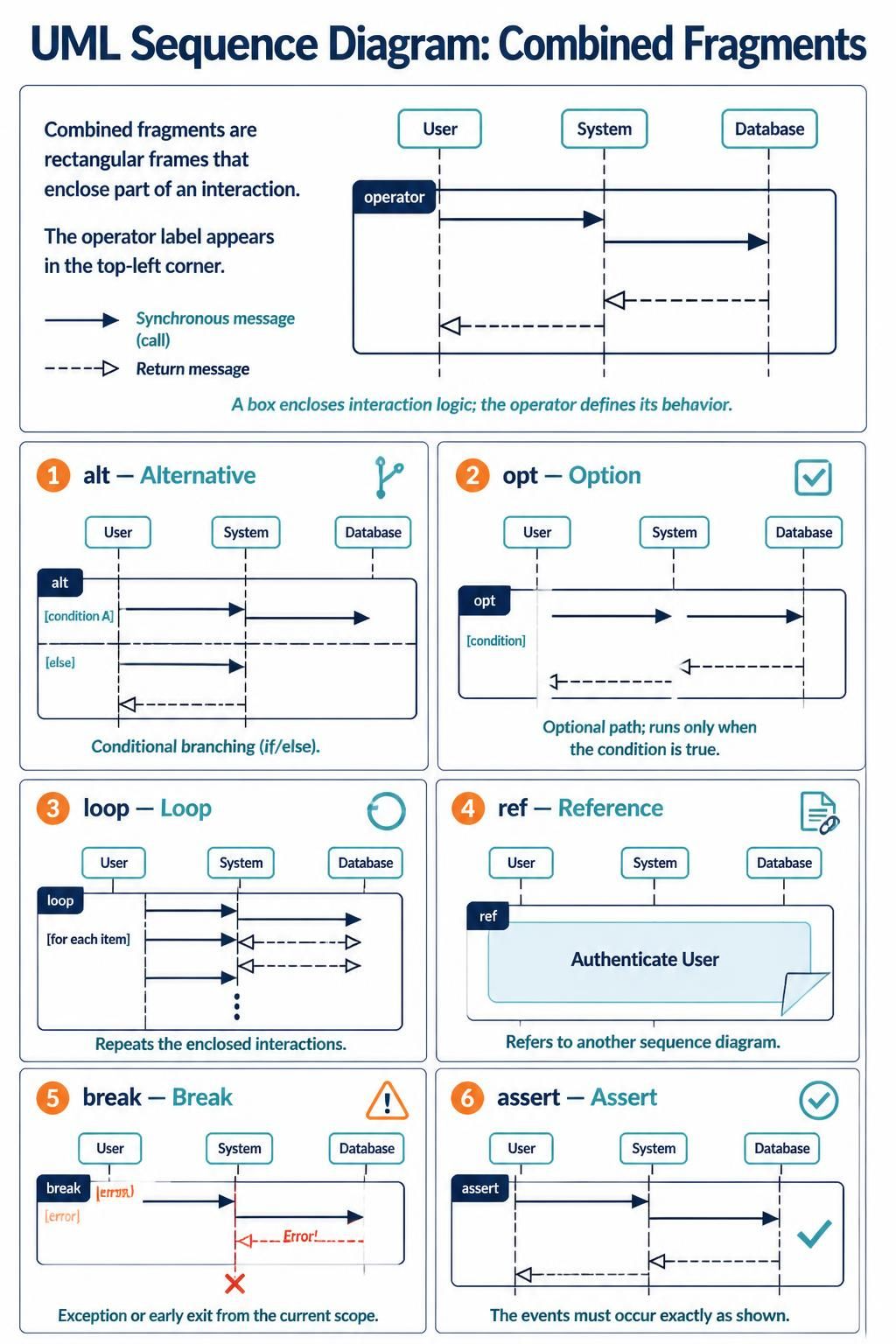
Imagine a sequence diagram as a blueprint for a conversation between system components. A Combined Fragment is a rectangular frame that encloses a specific portion of this interaction. It allows you to group messages together and apply specific behavioral rules to that group.
The defining characteristic of a combined fragment is the operator label found in the top-left corner of the frame. This label dictates how the enclosed logic executes. Whether the logic should repeat, branch based on a condition, or refer to an external process is determined entirely by this operator.
Core Concepts
- Frame: The rectangular box enclosing the interaction.
- Operator: The keyword in the top-left corner (e.g.,
loop,alt) defining behavior. - Occurrence Constraint: Conditions (e.g.,
[if user logged in]) that determine execution.
Essential Combined Fragment Operators
There are six primary operators used to structure complex logic in UML sequence diagrams. Let’s break down each one and see how it is applied in software architecture.
1. alt (Alternative)
The alt operator represents conditional branching, effectively modeling if/else logic. It divides the fragment into distinct regions (operands), separated by horizontal dashed lines. Only one of these regions will execute based on the evaluation of their respective conditions.
For example, if a user requests a file, the system might check for permissions. If permissions are granted, it serves the file; otherwise, it returns an error. The alt fragment captures this divergence perfectly.
2. opt (Option)
While alt handles branching, the opt (Option) operator represents a single optional path. The interaction inside the opt fragment occurs only if a specific condition evaluates to true. If the condition is false, the entire block is skipped, and the sequence continues below the fragment.
This is commonly used for non-critical features, such as sending a “Welcome Email” that might be skipped if the user has already received it, or logging a debug message only in a specific environment.
3. loop
Software often needs to process data in batches. The loop operator indicates that the enclosed interactions repeat. You can specify constraints to define the iteration logic:
- Maximum: The maximum number of times the loop can run.
- Minimum: The minimum number of times (e.g.,
min). - Condition: The logic that determines when to stop (e.g.,
while (hasMorePages)).
This is essential for modeling pagination, retry mechanisms, or iterating over a collection of items.
4. ref (Reference)
As systems grow, a single sequence diagram can become cluttered and unreadable. The ref operator allows you to reference another sequence diagram. This is crucial for modularity. Instead of drawing every single step for a complex process like “Authenticate User,” you can create a separate diagram for that process and simply link to it using a ref box.
5. break
The break fragment represents an exception or an early exit from the current scope. It is typically used to model error handling scenarios. If a specific error condition (like a database connection failure) occurs, the break fragment interrupts the normal flow and executes the error handling logic defined within it.
6. assert
The assert operator is a constraint that specifies the sequence of events within the fragment must occur exactly as shown. It acts as a verification point or a guarantee that a specific state is reached. If the events do not match the diagram, the assertion fails.
Tooling for UML Modeling
To effectively design these diagrams, you need robust engineering tools. Visual Paradigm is a premier platform for creating UML models, offering a comprehensive suite of features for software architects and developers.
Visual Paradigm: Your Modeling Partner
Visual Paradigm provides a powerful, user-friendly interface for designing complex sequence diagrams with Combined Fragments. Its “VPasCode” feature allows users to generate diagrams from code or vice versa, streamlining the documentation process.
Key capabilities of Visual Paradigm include:
- Drag-and-Drop Interface: Easily add lifelines, messages, and combined fragments (alt, loop, opt) to your canvas.
- Smart Layout: Automatically arranges messages to prevent overlap and maintain readability.
- Enterprise Integration: Seamlessly integrates with existing development workflows and supports multiple programming languages.
Conclusion
Combined Fragments are the building blocks of sophisticated UML sequence diagrams. By mastering alt, opt, loop, ref, break, and assert, you can accurately model the dynamic behavior of any software system. Whether you are planning a simple feature or architecting a distributed enterprise system, these tools ensure your diagrams are as robust as the code they describe.