
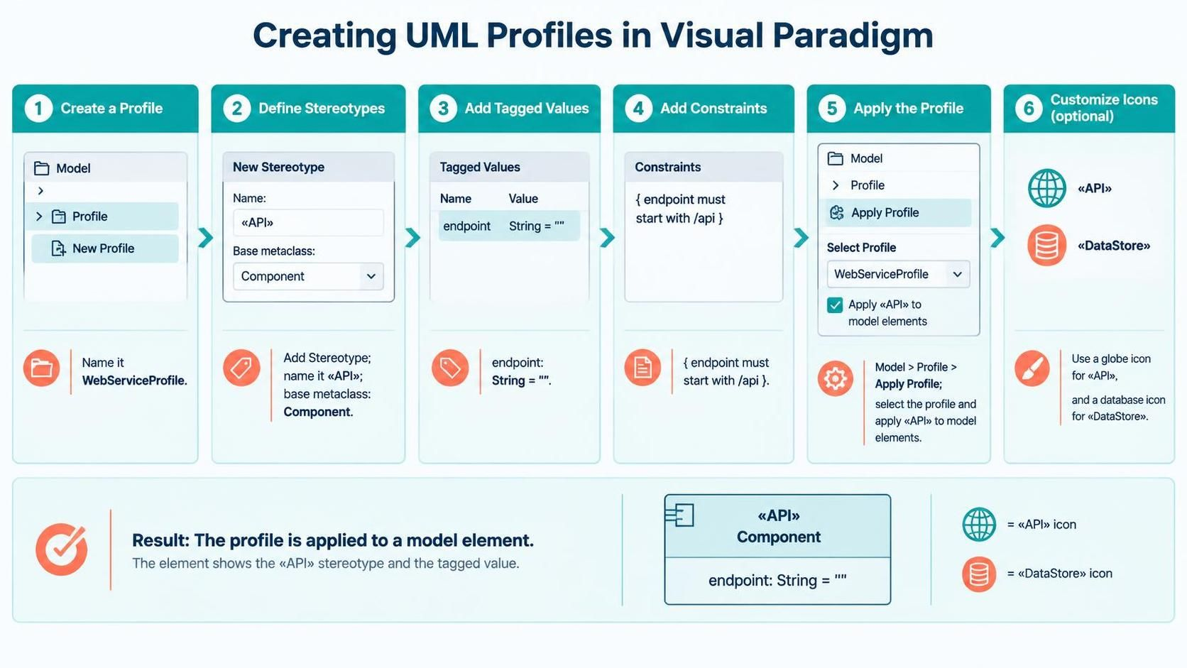
In the world of software engineering, standard UML diagrams often fall short when describing highly specific industry requirements or proprietary architectures. This is where UML Profiles become essential. A UML Profile is a mechanism that allows you to extend the UML metamodel without altering its core structure. It enables you to define custom notations, stereotypes, and constraints that are specific to your project’s domain.
Visual Paradigm provides a robust environment for creating and managing these profiles. In this tutorial, we will walk through the complete lifecycle of creating a domain-specific profile, applying it to your model, and visualizing it effectively.
Step 1: Initializing the Profile Structure
The first step in extending your modeling capabilities is to create a dedicated container for your custom definitions. Think of a Profile as a specific “dialect” of UML tailored for a specific task.
- Launch Visual Paradigm.
- Open your project model and locate the Model Browser.
- Navigate to the Model menu in the top toolbar.
- Select Profile followed by New Profile.
- You will be prompted to name your profile. For this example, we will name it
WebServiceProfile.
Step 2: Defining Custom Stereotypes
Stereotypes are the core of any profile. They allow you to reuse the properties of an existing UML metaclass but present it with a new name and potentially new semantics. For instance, a generic Component can be specialized into an API.
- Expand your newly created profile package in the Model Browser.
- Right-click on the package and select Add Stereotype.
- Name the stereotype (e.g.,
API). - Crucially, you must define the Base Metaclass. In the dropdown, select the UML element you are extending. For an API, Component is the standard base class.
Step 3: Enriching with Tagged Values
While standard UML elements have properties, they might lack specific data points required for your domain. Tagged values allow you to add arbitrary key-value pairs to your stereotypes.
- Open the stereotype editor for your new
APIstereotype. - Locate the Tagged Values section.
- Add a new tag. For our WebService example, we need to track the location of the service.
- Set the Name to
endpoint. - Set the Type to
String. - Provide a Default Value (e.g.,
""or"unknown").
Step 4: Enforcing Logic with Constraints
Validation is key to maintaining model integrity. You can define constraints to ensure that model elements adhere to specific rules. These can be written in natural language or formal languages like OCL (Object Constraint Language).
- Within the stereotype definition, find the Constraints field.
- Enter your rule. For a web service endpoint, a common rule is ensuring the path starts with a specific prefix.
- Example constraint:
{ endpoint must start with /api }.
Step 5: Applying the Profile to Your Model
Once your profile is built, it is currently “orphaned”—it exists but doesn’t affect your diagrams yet. You must apply it to the active model.
- Go to Model > Profile > Apply Profile.
- Select
WebServiceProfilefrom the list. - Ensure that the option to apply it to existing model elements is checked if you want to retroactively style your current diagram.
- Now, create a new Component in your diagram. Open its properties, and you should see the
<<API>>stereotype available in the dropdown menu.
Step 6: Visual Customization (Icons)
To make your diagrams intuitive for stakeholders, you can replace the generic UML icons with domain-specific imagery.
- Right-click your stereotype definition and look for Icon Configuration or Appearance.
- Assign a Globe Icon to the
<<API>>stereotype. - Assign a Database Icon to a hypothetical
<<DataStore>>stereotype. - Your diagram will now visually distinguish between standard components and your custom API elements instantly.
Summary: The Result
By following these steps, you have transformed a standard UML diagram into a specialized tool. When you apply the <<API>> stereotype to a Component, the diagram will display the custom icon, the stereotype tag, and the endpoint tagged value, providing a clear, concise, and semantically rich representation of your system architecture.