
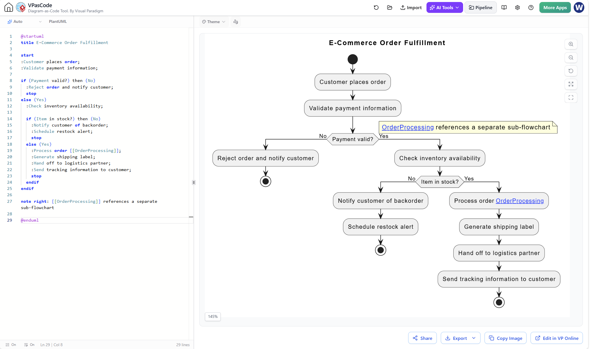
In the realm of systems engineering and software architecture, clarity is paramount. When designing complex workflows like an E-Commerce Order Fulfillment system, a single, flat diagram can quickly become a “spaghetti monster” that is impossible to read. This tutorial explores the power of hierarchical modeling using the VPasCode tool. We will deconstruct a real-world scenario where a high-level flow references a distinct sub-process, keeping the main architecture clean while allowing for granular detail elsewhere.
The Architecture of Complexity
The core challenge in modeling business logic is managing scale. If we were to draw every single step of an order fulfillment process—from payment validation to warehouse picking, packing, and shipping—on one canvas, the diagram would lose its value as a communication tool. Instead, we use a top-down approach.
The provided example demonstrates a classic State Machine or Activity Diagram pattern. It starts with the trigger (Customer places order) and branches based on critical business decisions (Payment validity, Inventory availability). However, the moment the process becomes too complex, we abstract it.
This is where the concept of [[OrderProcessing]] comes into play. By wrapping a label in double brackets, we signal to the diagramming engine that this is a reference to a sub-process. This keeps the parent diagram focused on the “Big Picture” logic without getting bogged down in the minutiae of the fulfillment steps.
Step-by-Step: Deconstructing the Model
Let’s walk through the logic flow presented in the diagram, analyzing how the code translates into visual behavior.
1. Initialization and Entry
Every diagram needs a definitive start and stop. In the code, this is handled by the start and stop keywords. The flow initiates with the customer interaction.
start
:Customer places order;
:Validate payment information;
2. Conditional Logic (The Payment Gate)
The first major decision point is payment validation. In PlantUML, this is achieved using the if statement. The syntax allows for explicit “Yes” and “No” branches, which makes the resulting flowchart highly readable.
if (Payment valid?) then (No)
  :Reject order and notify customer;
  stop
else (Yes)
  :Check inventory availability;
endif
Notice how the stop keyword is used immediately after the rejection path. This signifies a termination of the current flow, ensuring the diagram correctly represents an aborted transaction.
3. Nested Decision Making
Once the payment is validated, the system must check if the item is actually available. This is a nested decision. We do not need a new code block to start; we simply indent the next if statement inside the else (Yes) block of the previous logic.
if (Item in stock?) then (No)
  :Notify customer of backorder;
  :Schedule restock alert;
  stop
else (Yes)
  :Process order [[OrderProcessing]];
  ...
4. The Power of Sub-Processes
The most critical part of this example is line 19:
:Process order [[OrderProcessing]];By using the double brackets [[...]], we tell VPasCode to treat “OrderProcessing” not just as text, but as a hyperlink or a reference to a separate diagram file. This is the definition of modularity in modeling. It allows teams to work on the “Order Processing” sub-flowchart independently from the “Payment Validation” logic.
5. Finalizing the Flow
The remaining steps in the “Yes” branch represent the standard fulfillment actions: generating labels, handing off to logistics, and notifying the customer. These are simple activity nodes that conclude the successful path of the workflow.
:Generate shipping label;
:Hand off to logistics partner;
:Send tracking information to customer;
stop
Why Use VPasCode for This?
The VPasCode tool bridges the gap between text-based coding and visual design. By writing the diagram in code, you gain version control capabilities. You can track changes to the logic flow in Git just like you would with source code, rather than fighting with the alignment of boxes and arrows in a traditional GUI editor. This approach ensures that your architectural documentation remains consistent and maintainable.
Conclusion
Effective system architecture is about abstraction. By using VPasCode to generate diagrams from text, you can create complex, hierarchical workflows that are easy to read and maintain. The “E-Commerce Order Fulfillment” example proves that even simple syntax can model sophisticated business logic, provided you leverage the power of sub-processes to manage complexity.