
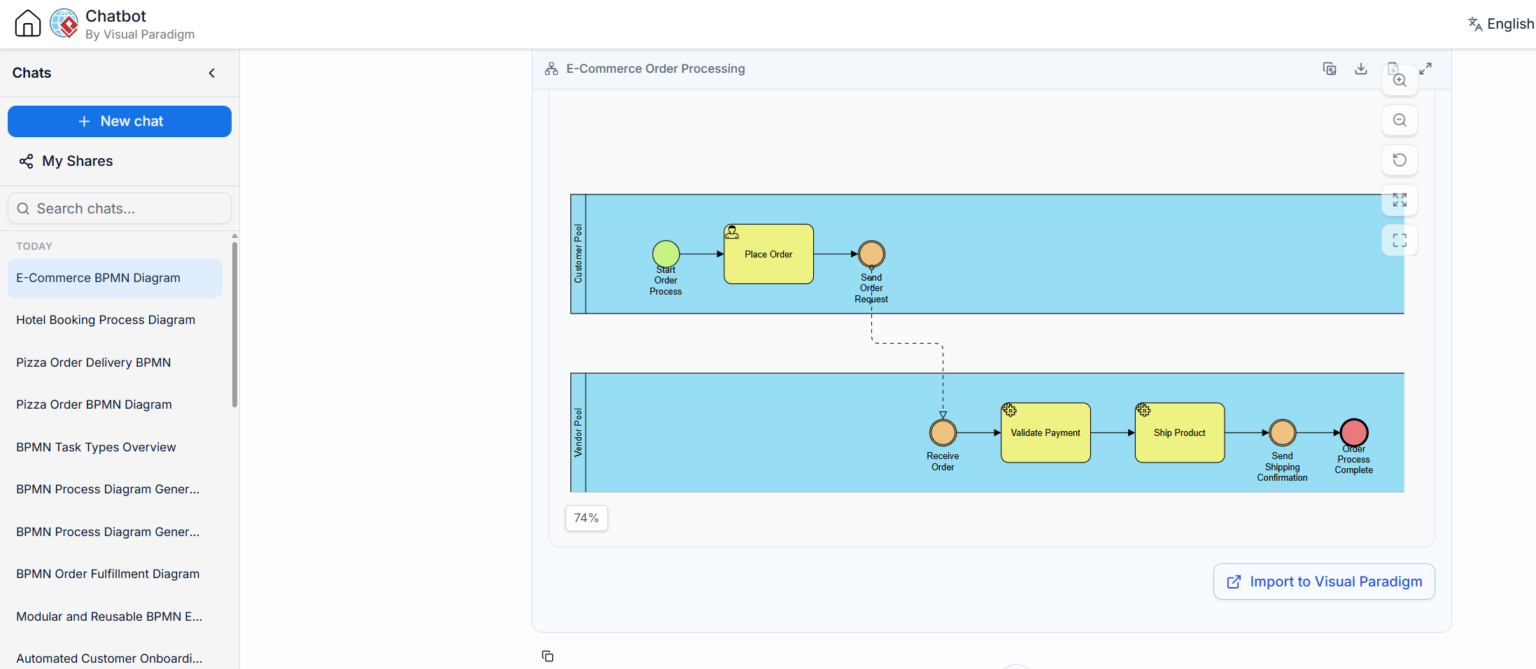
In the realm of business process management, clarity is currency. When designing a system as critical as an e-commerce order fulfillment loop, ambiguity can lead to financial loss and customer dissatisfaction. This tutorial explores the architecture of an E-Commerce Order Processing scenario, breaking down how to correctly model interactions between a Customer and a Vendor using Business Process Model and Notation (BPMN).
Based on the visual data provided, we will dissect the use of Sequence Flows for internal logic, Message Flows for cross-pool communication, and the strict syntax rules required to maintain a valid process model.
The Scenario: A Two-Party Interaction
The core of this diagram represents a transaction between two distinct entities: the Customer and the Vendor. In BPMN, these entities are represented as Pools. A Pool acts as a container that separates the responsibilities and processes of different organizations or participants.
1. The Customer Pool (The Initiator)
The upper blue container represents the Customer Pool. The process here is initiated by the customer’s intent to purchase. The flow is linear and internal to the customer’s decision-making process:
- Start Event: A green circle labeled “Start Order Process” signifies the trigger. This is the moment the customer decides to buy.
- Task: A yellow rectangle labeled “Place Order” represents the action taken by the customer.
- Intermediate Event: A circular event labeled “Send Order Request” acts as the bridge. It indicates that the customer has completed their internal steps and is now ready to transmit information to the vendor.
2. The Vendor Pool (The Executor)
The lower blue container represents the Vendor Pool. This is where the heavy lifting of the business process occurs. The vendor’s system is passive until it receives an external trigger:
- Receive Event: A circular event labeled “Receive Order” waits for the message from the customer. This is the synchronization point where the Vendor’s process begins.
- Tasks: The process moves through “Validate Payment” and “Ship Product.” These represent the operational logic of the vendor’s system.
- End Event: The red circle labeled “Order Process Complete” signifies the termination of the workflow once the product has been shipped.
Connecting the Pools: The Role of Message Flows
The most critical architectural element in this diagram is the connection between the Customer and the Vendor. In the provided screenshot, this is depicted as a dashed line with an open arrowhead.
This is a Message Flow. It is the specific BPMN construct used to show communication between two different pools. It represents the transmission of a business document or data—in this case, the Order Request.
Why Not a Sequence Flow?
A common mistake for beginners is connecting tasks across different pools using a solid line (Sequence Flow). In BPMN syntax, this is strictly forbidden. Sequence Flows define the execution order of tasks inside a single participant. If you use a solid line to cross a pool boundary, the diagram becomes syntactically invalid and confusing. It implies that the Vendor’s system is “controlling” the Customer’s system, which is logically impossible in this context.
Visual Paradigm Validation
When using tools like Visual Paradigm, this distinction is enforced by the engine. If you attempt to draw a solid sequence flow from the “Place Order” task to the “Receive Order” event, the tool will typically highlight the error in red or refuse to connect the shapes. This ensures that the resulting diagram is executable and logically sound.
Data Flow vs. Process Flow
While the image focuses on the control flow (the movement of the process), a complete BPMN model also considers data. The text context highlights the relationship between tasks and data objects:
- Input Data: The “Validate Payment” task relies on external data, such as the Customer Credit Record. In a full diagram, this would be a dotted line connecting a data object to the task.
- Output Data: The “Ship Product” task generates a Shipping Manifest. This is the data artifact produced by the execution of the task.
It is vital not to confuse these Data Associations (dotted lines) with Sequence Flows (solid lines). Data associations show what information is needed; sequence flows show when the action happens.
Best Practices for Model Accuracy
To ensure your diagrams are professional and error-free, adhere to the following architectural guidelines:
- Respect Pool Boundaries: Never cross a pool boundary with a solid line. Always use a dashed Message Flow for external communication.
- Define Clear Triggers: Ensure that every process start in a pool (like “Receive Order”) is triggered by an incoming message or event. Do not leave internal processes floating without a cause.
- Use Tooling Features: Leverage the built-in validation of Visual Paradigm. Use the “Import to Visual Paradigm” button to verify that the AI-generated or chat-generated logic adheres to strict BPMN standards.
Conclusion
Understanding the distinction between internal logic and external communication is the foundation of effective process modeling. By correctly utilizing Message Flows to bridge the gap between the Customer and the Vendor, you create a diagram that accurately reflects the reality of the business interaction. This clarity is essential for stakeholders, developers, and AI assistants alike to understand the system architecture.
Whether you are manually crafting diagrams in Visual Paradigm or utilizing AI chatbots to accelerate the process, keeping these syntax rules in mind will prevent common pitfalls and ensure your E-Commerce process model is robust, executable, and clear.