
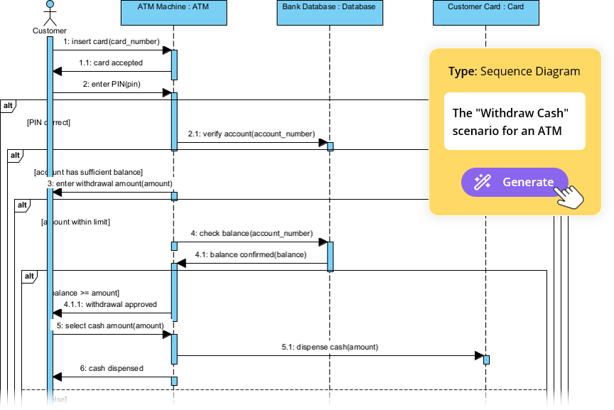
In the realm of software engineering, understanding how objects interact over time is crucial for designing robust systems. This tutorial delves into the specific mechanics of an ATM “Withdraw Cash” scenario, visualized through a UML Sequence Diagram. By leveraging the Prompt-to-Diagram Generation Engine found in tools like Visual Paradigm, we can transform complex textual requirements into precise, professional-grade diagrams instantly.
Understanding the Core Components
A Sequence Diagram is a type of interaction diagram because it describes how—and in what order—a group of objects works together. In the diagram above, we see the orchestration of a transaction between a human user and several system components.
1. The Participants (Lifelines)
Vertical dashed lines represent the lifelines of the participating objects. Each object is instantiated at the top:
- Customer: The actor initiating the interaction. Note the stick figure icon, standard for human actors in UML.
- ATM Machine : ATM: The physical interface device handling the user’s input.
- Bank Database : Database: The backend system storing account information and balances.
- Customer Card : Card: The data entity representing the physical card’s information.
2. Activation Bars
The thin, vertical rectangles on the lifelines are called activation bars. They indicate the period during which an object is performing an action or waiting for a response. For example, the ATM Machine has an activation bar when it is processing the PIN entry.
Decoding the Interaction Flow
The horizontal arrows represent messages exchanged between objects. The flow moves from top to bottom, representing the passage of time.
Step 1: Authentication
The process begins with the customer inserting their card. The message insert card(card_number) is sent to the ATM. The system responds with card accepted, followed by the user entering their PIN (enter PIN(pin)).
Step 2: Conditional Logic (Alt Frames)
Real-world logic is rarely linear. The diagram utilizes Alt (Alternative) frames to handle decision points. Look for the rectangular boxes with a dashed line and the keyword alt at the top left:
- First Alt Frame: The system checks if the PIN is correct
[PIN correct]. If the condition is false, the interaction stops or branches differently (not shown in this specific success path). - Second Alt Frame: The system verifies if the
[account has sufficient balance]. If not, the transaction is halted. - Third Alt Frame: A check for
[amount within limit]ensures the withdrawal does not exceed daily caps.
Implementing with AI
Traditionally, drawing this diagram required manually dragging boxes, aligning lifelines, and drawing arrows. With the Prompt-to-Diagram Generation Engine, the workflow is reversed:
- Input: You provide a natural language description, such as “A user inserts a card, enters a PIN, checks if the account has sufficient balance, and withdraws cash if valid.”
- Processing: The AI identifies entities (Customer, ATM, Database) and logical links.
- Output: The engine generates the full sequence diagram with correct alt frames and message numbering (e.g., 1, 1.1, 2) automatically.
Technical Implementation (PlantUML Example)
For those interested in the underlying syntax that defines this structure, here is how the logic is represented in code. This format is commonly used by AI engines to render the visual diagram.
@startuml
autonumber
actor Customer
participant "ATM Machine" as ATM
participant "Bank Database" as DB
participant "Customer Card" as Card

Customer -> ATM: 1: insert card(card_number)
ATM -> ATM: 1.1: card accepted
Customer -> ATM: 2: enter PIN(pin)

alt PIN correct
    ATM -> DB: 2.1: verify account(account_number)

    alt account has sufficient balance
        Customer -> ATM: 3: enter withdrawal amount(amount)

        alt amount within limit
            ATM -> DB: 4: check balance(account_number)
            DB -> ATM: 4.1: balance confirmed(balance)

            alt balance >= amount
                ATM -> Customer: 4.1.1: withdrawal approved
                ATM -> ATM: 5: select cash amount(amount)
                ATM -> DB: 5.1: dispense cash(amount)
                ATM -> Customer: 6: cash dispended
            end
        end
    end
end
@enduml
Conclusion
This “Withdraw Cash” scenario demonstrates how critical conditional logic is in system design. By using the AI generation capabilities, developers can focus less on the mechanics of drawing and more on the semantic correctness of the interaction flows, ensuring that edge cases like insufficient funds are handled gracefully.