
In the world of software engineering and system architecture, understanding the “big picture” is crucial, but knowing the specific state of a system at a precise moment is even more critical. While class diagrams define the blueprint of your system, Object Diagrams act as the blueprint’s snapshot in time. This tutorial explores how to use Object Diagrams within Visual Paradigm to validate system architecture, specifically analyzing the interaction between boundary, control, and entity layers in an inspection system.
What is an Object Diagram?
An Object Diagram is a static structural diagram that shows a snapshot of the detailed state of a system at a point in time. It is essentially an instance of a Class Diagram. While a class diagram shows the general structure (the rules), an object diagram shows the actual objects (the data) and their links.
Consider the difference this way:
- Class Diagram: Defines a “Customer” and an “Order” and states that a Customer can place Orders.
- Object Diagram: Shows “Customer: John Doe” specifically linked to “Order: #12345” right now.
Analyzing the Inspection System Architecture
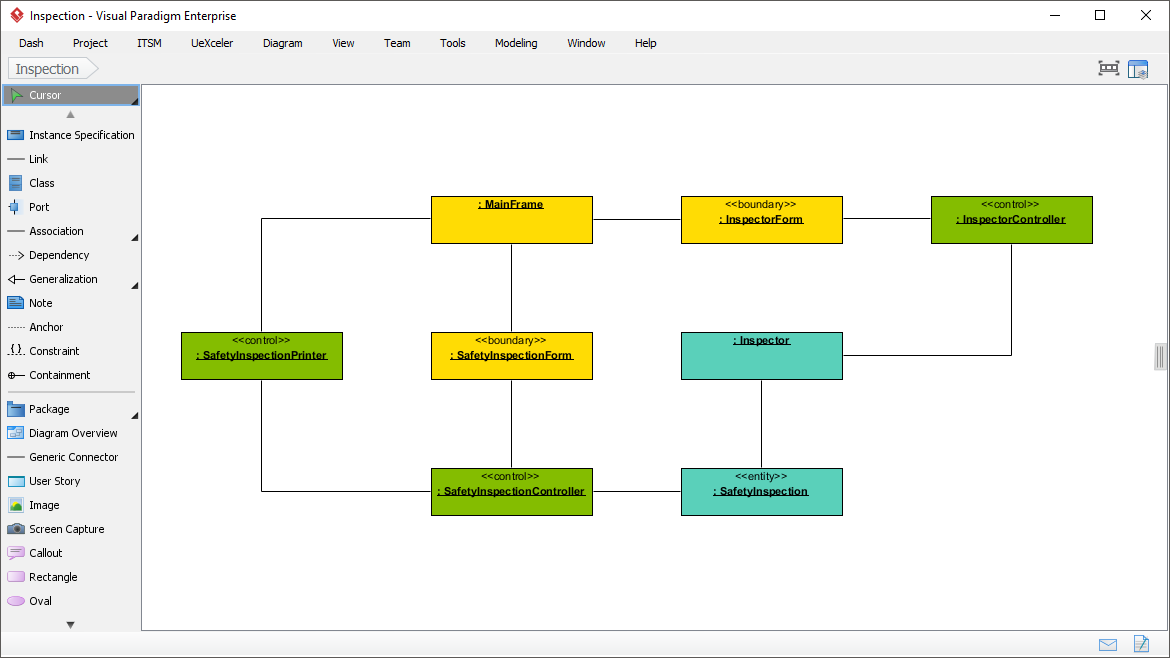
Looking at the provided architecture diagram from Visual Paradigm, we can see a classic Model-View-Controller (MVC) or 3-Tier architecture applied to an “Inspection” module. This diagram illustrates how different parts of the application communicate.
The Three Layers of the System
The diagram utilizes standard stereotypes to categorize objects into specific roles:
- Boundary Objects (Yellow): These represent the user interface or the interaction layer.
MainFrame: The primary container for the application.InspectorForm: A specific view for managing inspector details.SafetyInspectionForm: The view dedicated to the inspection data.
- Control Objects (Green): These represent the business logic and flow of the application. They coordinate the boundary and entity objects.
InspectorController: Manages the logic for the inspector form.SafetyInspectionPrinter: Handles the logic related to printing reports.SafetyInspectionController: Manages the core logic for the safety inspection process.
- Entity Objects (Teal): These represent the data layer, storing information that persists over time.
Inspector: Stores data about the person conducting the inspection.SafetyInspection: Stores the actual data regarding the safety check.
Understanding the Relationships
The lines connecting these boxes represent associations or links. In an object diagram, these links show how the specific instances are related.
- MainFrame to InspectorForm: The main window contains the inspector form.
- InspectorForm to InspectorController: The user interface passes user actions to the controller for processing.
- SafetyInspectionController to SafetyInspection: The controller accesses and modifies the data stored in the entity object.
This specific layout helps architects visualize how a user interaction (Boundary) triggers a process (Control) that updates a record (Entity). It validates that the architecture is sound before any code is written.
Using Visual Paradigm for Object Modeling
Visual Paradigm is a powerful enterprise tool that simplifies the creation of these diagrams. It allows you to switch between Class and Object views seamlessly. To create the type of diagram shown in the image, you would typically follow these steps:
- Create a Class Diagram: Define your classes (Inspector, SafetyInspection) and their types (Boundary, Control, Entity).
- Generate Objects: In Visual Paradigm, you can instantiate objects from your classes. This is often done by right-clicking a class and selecting “Create Object” or “Create Instance.”
- Apply Stereotypes: Assign the specific stereotypes like <<boundary>> or <<control>> to the objects to color-code them and define their architectural role.
- Link Instances: Draw associations between the specific objects to show the runtime state.
The tool’s palette, visible in the image, provides quick access to tools like Instance Specification, Link, and Port, ensuring that your diagrams are accurate representations of the system’s behavior.
Key Takeaways
Object diagrams are not just pretty pictures; they are a vital part of the design process. They provide a concrete example of how the abstract rules in a class diagram are applied in the real world. By using Visual Paradigm to model these interactions, you ensure that your system’s architecture—specifically the flow between user interfaces, business logic, and data—is robust and well-connected.