
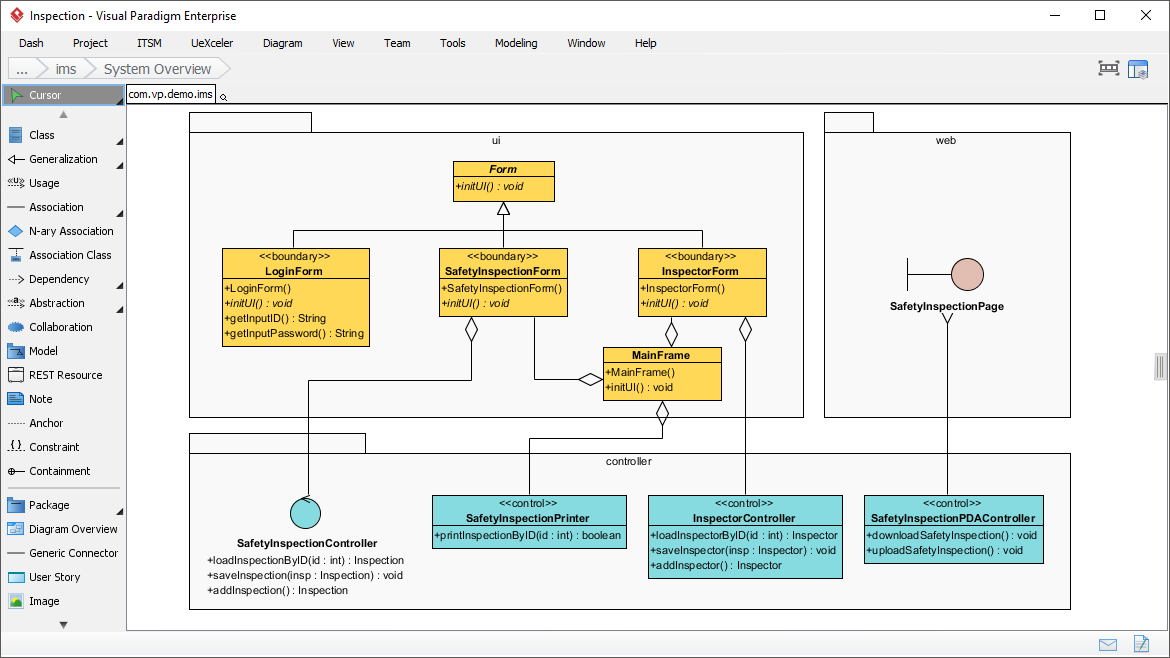
In the world of software engineering, visualizing how a system is built is just as critical as writing the code itself. The screenshot provided illustrates a System Overview diagram created within Visual Paradigm. This specific type of diagram is a powerful tool for depicting the high-level structure of an application using the classic Model-View-Controller (MVC) architecture. By organizing the system into distinct layers, developers can ensure a clean separation of concerns, making the software easier to maintain and scale.
This tutorial will guide you through the components visible in this diagram, explain the architectural patterns at play, and demonstrate how to use Visual Paradigm to model these relationships effectively.
Understanding the Architecture: The MVC Pattern
The diagram clearly separates the system into three primary packages or folders, which correspond to the three layers of the MVC pattern. This architectural style is fundamental to modern application development, particularly in enterprise environments.
- View (UI Layer): Represented by the ui package. This layer handles the user interface and interaction. It is responsible for displaying data to the user and capturing user input.
- Controller (Logic Layer): Represented by the controller package. This layer acts as the intermediary. It processes user input from the View, interacts with the data (Model), and updates the View accordingly. In this diagram, the controllers are explicitly labeled with the stereotype
<<control>>. - Model (Data Layer): Represented by the web package. This layer manages the data and business logic of the application. In this specific context, it appears to handle web-based data structures like
SafetyInspectionPage.
Deep Dive: The User Interface (View)
Inside the ui package, we observe a hierarchy of classes that form the visual skeleton of the application. The diagram highlights a base class named Form, which serves as a parent for several specific screen implementations.
The relationship between Form and its children—LoginForm, SafetyInspectionForm, and InspectorForm—is depicted using a generalization (inheritance) arrow. This means that all these forms share common behaviors defined in the Form class, such as initUI(), but also possess unique attributes and methods specific to their function.
Furthermore, the diagram uses the stereotype <<boundary>> for classes like LoginForm. In UML, this stereotype typically signifies a class that interacts with external actors or systems, acting as a boundary for the application.
Deep Dive: The Controllers (Logic)
The controller package is the engine room of the application. It contains classes that dictate the flow of the application. The diagram showcases three distinct controllers:
- SafetyInspectionController: A specialized control element (indicated by the circle shape) that manages the core inspection data, including loading and saving inspections.
- SafetyInspectionPrinter: A controller dedicated specifically to the logic of printing inspection reports by ID.
- InspectorController: Handles the lifecycle of inspectors, allowing users to add new inspectors or save updated information.
- SafetyInspectionPDACo…: A controller that handles file operations, specifically downloading and uploading safety inspection files.
Deep Dive: The Model (Data)
The web package contains the SafetyInspectionPage entity. This represents the data model, likely corresponding to a database table or a web service resource. It is connected to the controllers, indicating that the logic layer interacts with this data layer to retrieve or persist information.
Decoding the Relationships
Visual Paradigm allows you to draw precise relationships between these layers. The lines connecting the ui package to the controller package are particularly telling. The diagram uses a diamond shape at the end of the line connecting Form (specifically SafetyInspectionForm) to MainFrame. This represents an Aggregation relationship.
In this context, it suggests that the MainFrame container holds or aggregates these forms. It is a “has-a” relationship where the parts (forms) can exist independently of the whole (the main frame), but logically, the main frame manages them.
Tooling: Visual Paradigm
The screenshot clearly indicates the use of Visual Paradigm (specifically the Enterprise edition), a robust UML modeling tool. Here is why it is an excellent choice for this type of architectural work:
- Visual Modeling: It provides a drag-and-drop interface for creating UML diagrams, including Class, Component, and Use Case diagrams.
- Code Engineering: Visual Paradigm supports forward engineering (generating code from diagrams) and reverse engineering (importing existing code to generate diagrams), ensuring your documentation stays in sync with your application.
- Enterprise Features: The interface shown includes tabs for “Dash”, “Project”, and “ITSM”, suggesting it supports full lifecycle management, not just diagramming.
Whether you are designing a complex enterprise system or a simple web application, utilizing Visual Paradigm to map out your System Overview ensures that your team has a clear, shared understanding of how the pieces fit together.