
Introduction to BPMN and Visual Paradigm
Business Process Model and Notation (BPMN) is the industry standard for visualizing business workflows. It acts as a bridge between business stakeholders and technical developers, providing a graphical representation of the flow of information and tasks within a system. Unlike traditional flowcharts, BPMN includes specific semantics that define how events start, stop, and control the flow of a process.
In this tutorial, we will deconstruct a complex workflow diagram created using Visual Paradigm. We will analyze the “Nobel Prize Nomination Process” to understand how to model multi-party collaboration, data storage, and decision logic using BPMN 2.0 standards.
Understanding the System Architecture
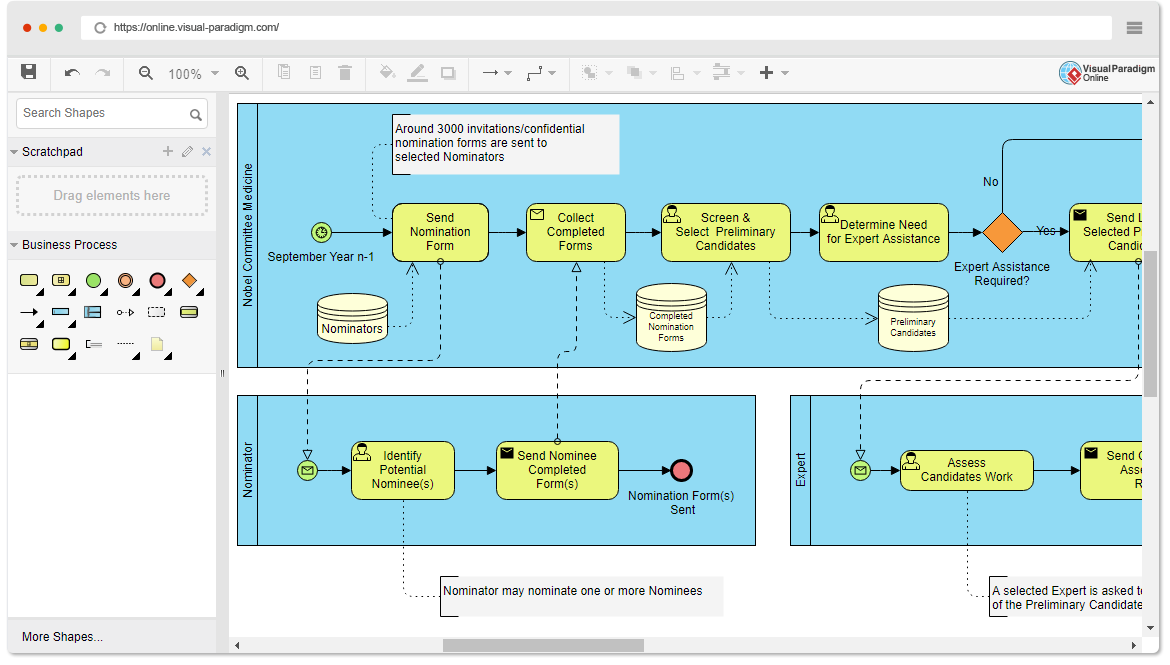
The diagram illustrates a sophisticated process involving three distinct roles, known as Pools in BPMN terminology. These pools represent the high-level boundaries of the process and the entities responsible for specific tasks.
1. The Pools (Organizational Boundaries)
The architecture is divided into three main vertical containers:
- Nobel Committee Medicine: The central authority responsible for the overall process, screening, and final selection.
- Nominator: External experts or individuals who submit potential candidates.
- Expert: Specialists who evaluate the work of the nominated candidates.
2. The Swimlanes (Swimlanes)
While the diagram primarily uses Pools to separate organizations, the internal flow within the “Nobel Committee Medicine” pool represents a logical sequence of operations managed by the committee. In BPMN, these horizontal or vertical strips are often called Swimlanes, used to assign tasks to specific roles within a single organization.
Detailed Breakdown of Modeling Concepts
To understand how this diagram functions, we must analyze the specific BPMN symbols and their interactions.
A. Start and End Events
Every BPMN process must begin and end. The diagram uses different shapes to denote the state of these events:
- Start Event (Green Circle with Envelope): In the “Nominator” lane, the process starts with a Message Start Event. This indicates that the process is triggered by the receipt of a specific message or form (the nomination form).
- End Event (Red Circle): The “Nominator” lane ends with a solid red circle, representing a Terminate End Event. This signifies that the process concludes successfully after the form is sent.
B. Intermediate Events and Data Objects
BPMN processes often involve waiting for information or interacting with databases. The diagram features Intermediate Events (circles with icons) that represent delays or message exchanges. For example, the “Collect Completed Forms” step involves an intermediate event that likely waits for the forms to arrive.
Additionally, the Data Store symbols (cylinders) represent persistent storage. The “Nominators” and “Preliminary Candidates” cylinders indicate where data is saved and retrieved throughout the lifecycle of the process.
C. Gateways (Decision Logic)
One of the most critical features of BPMN is the Gateway, which controls the flow of the process based on conditions. The diagram features a Diamond shape labeled “Expert Assistance Required?”. This is an Exclusive Gateway (XOR).
- Yes Path: If assistance is required, the flow moves to the “Expert” pool.
- No Path: If no assistance is needed, the flow bypasses the expert and proceeds to the final selection phase.
D. The “Expert” Collaboration
The “Expert” pool demonstrates a parallel interaction. When the committee determines that expert assistance is needed, a message is sent to the Expert. The Expert then performs the task “Assess Candidates Work” and sends the assessment back. This interaction is modeled using a Message Flow (dashed line with an arrow), distinct from the solid sequence flows used within a single pool.
Step-by-Step Process Walkthrough
Let’s trace the path of a single nomination through this system:
- Initiation: The process begins in September of the previous year (Year n-1). The Nobel Committee sends out nomination forms to selected Nominators.
- Nomination: The Nominator identifies a potential nominee and sends the completed form. This action is logged in the system.
- Collection & Screening: The Committee collects these forms and screens the preliminary candidates. This involves checking the data against criteria stored in the “Preliminary Candidates” data store.
- Decision Point: The Committee reaches the “Determine Need for Expert Assistance” gateway.
- Expert Review (Conditional): If the gateway evaluates to “Yes”, the process delegates the task to the Expert pool. The Expert assesses the candidate’s work.
- Final Selection: Once the expert review is complete (or if it wasn’t needed), the Committee proceeds to “Send List of Selected Preliminary Candidates”.
Visual Paradigm Tooling Features
The diagram above was created using Visual Paradigm, a comprehensive modeling tool that supports BPMN 2.0. Here is how Visual Paradigm facilitates this level of complexity:
1. Drag-and-Drop Modeling
The interface allows users to drag shapes from the “Scratchpad” or “Business Process” palette directly onto the canvas. This WYSIWYG (What You See Is What You Get) approach makes it easy to build complex diagrams without writing code.
2. Shape and Connector Tools
Visual Paradigm provides advanced shapes and connectors. The diagram shows the use of specific connectors for message flows (dashed lines) versus sequence flows (solid lines). The tool automatically handles the routing of these lines to ensure the diagram remains clean and readable.
3. Automated Layouts
For processes with many steps, Visual Paradigm offers automated layout features. This ensures that the diagram elements are organized logically, preventing lines from crossing unnecessarily and making the process easier to read.
4. Validation and Standards
One of the key benefits of using Visual Paradigm is its built-in validation rules. The tool ensures that the BPMN diagram adheres to the BPMN 2.0 standard, preventing common modeling errors such as orphaned tasks or invalid gateway configurations.
Summary of Flow Objects
To summarize the modeling elements used in this diagram:
- Events: Represent the timing of the process (Start, Intermediate, End).
- Activities: Represent the actual work being done (Send Form, Screen Candidates, Assess Work).
- Gateways: Represent decision points (Expert Assistance Required).
Conclusion
Creating a BPMN diagram like the Nobel Prize Nomination Process requires a clear understanding of the workflow and the tools available to represent it. Visual Paradigm provides a robust environment for modeling these complex interactions, ensuring that business processes are accurately documented and easily understood by all stakeholders.
By leveraging the features of Visual Paradigm, from its intuitive drag-and-drop interface to its advanced validation tools, organizations can streamline their business processes, improve operational efficiency, and foster better collaboration between different departments and external partners.