
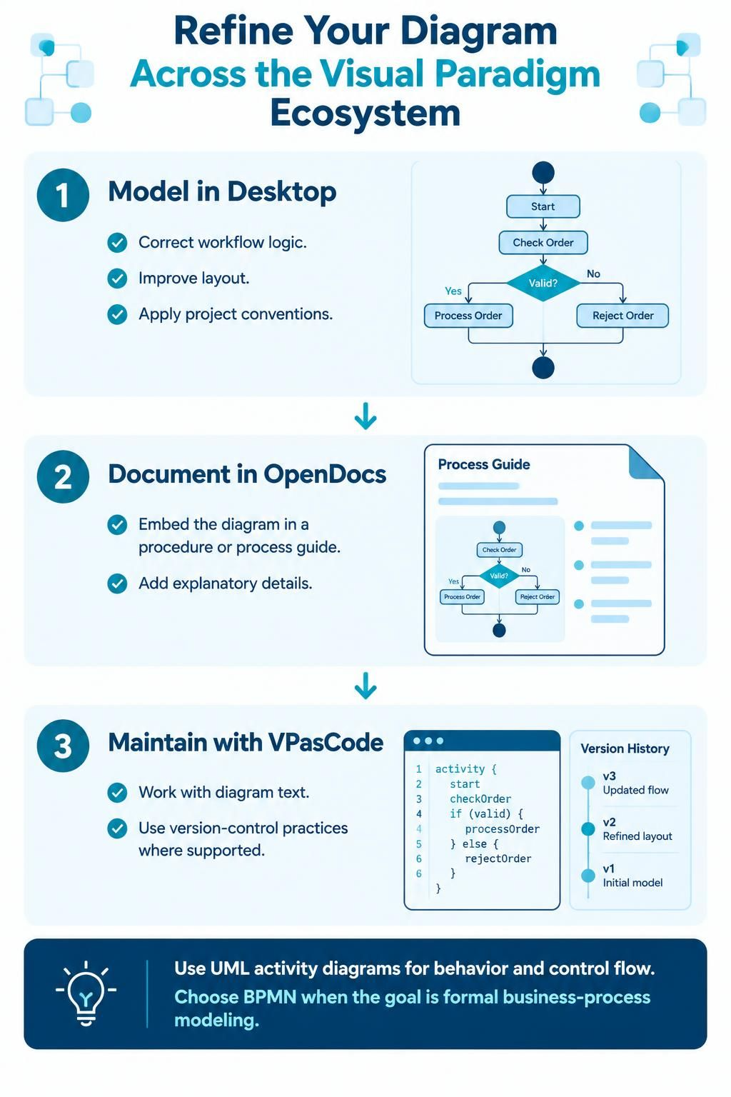
In the modern software development lifecycle, the gap between abstract ideas and executable specifications often leads to communication breakdowns. Visual Paradigm addresses this challenge by offering an integrated ecosystem where diagrams are not static images, but living artifacts that can be modeled, documented, and version-controlled.
This tutorial explores the strategic workflow for refining AI-generated or initial UML activity diagrams. We will walk through the three pillars of this process: modeling in Desktop, documenting in OpenDocs, and maintaining changes with VPasCode.
Phase 1: Modeling in Desktop – The Foundation
The journey begins in the Visual Paradigm Desktop environment. While AI tools can generate a diagram to serve as a starting point, it often lacks the precision required for production systems. The first step involves refining this initial draft.
When you import an AI-generated diagram or begin a new model, you must act as the architect of the logic. This phase focuses on three critical areas:
- Correcting Workflow Logic: AI might generate a plausible flow, but it often misses edge cases. You must verify decision diamonds (e.g., “Valid?”) and ensure all paths—both “Yes” and “No”—lead to a logical conclusion.
- Improving Layout: Automated layouts often result in tangled connections. Desktop provides tools to manually rearrange nodes, ensuring the diagram is readable and follows standard “top-to-bottom” or “left-to-right” conventions.
- Applying Project Conventions: Every organization has a style guide. This is the place to standardize notation, ensuring that your UML activity diagrams align with the team’s specific modeling standards.
The image below illustrates the refinement of a basic “Order Check” flow. Initially, it might be a simple text description, but in Desktop, it becomes a structured UML activity diagram with clear start and end nodes.
// Conceptual UML Activity Diagram Structure
activityDiagram {
    [*] --> Start
    Start --> CheckOrder
    CheckOrder --> Decision{Valid?}
    Decision -- Yes --> ProcessOrder
    Decision -- No --> RejectOrder
    ProcessOrder --> [*]
    RejectOrder --> [*]
}
Phase 2: Documenting in OpenDocs – Bridging the Gap
A diagram is powerful, but it is not always self-explanatory. Complex business rules or regulatory requirements often cannot be visualized within the constraints of a flowchart. This is where Visual Paradigm OpenDocs becomes essential.
OpenDocs allows you to treat the diagram as a component within a larger narrative. Instead of exporting a PNG and pasting it into a Word document, you embed the live diagram directly into a procedure or process guide.
- Embedding Context: Place the refined diagram side-by-side with written instructions. This allows the reader to see the “big picture” flow while reading the specific details.
- Adding Explanatory Details: Use the text editor to explain steps that need more granularity than the diagram can show. For example, if the diagram has a “Process Order” node, the document can contain a step-by-step breakdown of what data is validated during that process.
Phase 3: Maintaining with VPasCode – Version Control for Models
One of the most significant challenges in model-driven engineering is tracking changes. When multiple stakeholders work on a diagram, the “compare and merge” process can be difficult. Visual Paradigm solves this with VPasCode, a code-based representation of your diagrams.
VPasCode allows you to treat diagram definitions as text files. This enables the use of standard version-control practices (like Git) for your visual models.
Why Use VPasCode?
- Text-Based Editing: You can describe your activity diagrams using a structured language that is readable and writable.
- Version History: Because the model is essentially text, you can see exactly what changed between versions (e.g., “Refined layout” vs. “Updated flow logic”).
- Collaboration: Developers and architects can review changes to the logic without needing to open the heavy graphical interface.
The code snippet below demonstrates how a workflow might look in VPasCode, allowing for precise version tracking.
// VPasCode Example for Version Control
activity {
    start
    checkOrder
    if (valid) {
        processOrder
    } else {
        rejectOrder
    }
}

// Version Log
// v1: Initial model created
// v2: Refined layout applied
// v3: Updated flow logic for rejection path
Choosing the Right Notation: UML vs. BPMN
While the workflow described above applies to both, it is crucial to select the correct notation for your goal. Visual Paradigm provides clear guidance on this distinction:
- Use UML Activity Diagrams: These are best suited for describing behavior and control flow within a software system. They focus on the logic of the process (e.g., “If X, then Y”).
- Choose BPMN (Business Process Model and Notation): If your primary goal is formal business-process modeling, especially when dealing with complex organizational interactions, swimlanes, and regulatory compliance, BPMN is the industry standard.
By mastering the flow from Desktop to OpenDocs and finally to VPasCode, you ensure that your diagrams are not just pictures, but a robust, version-controlled part of your engineering documentation.