
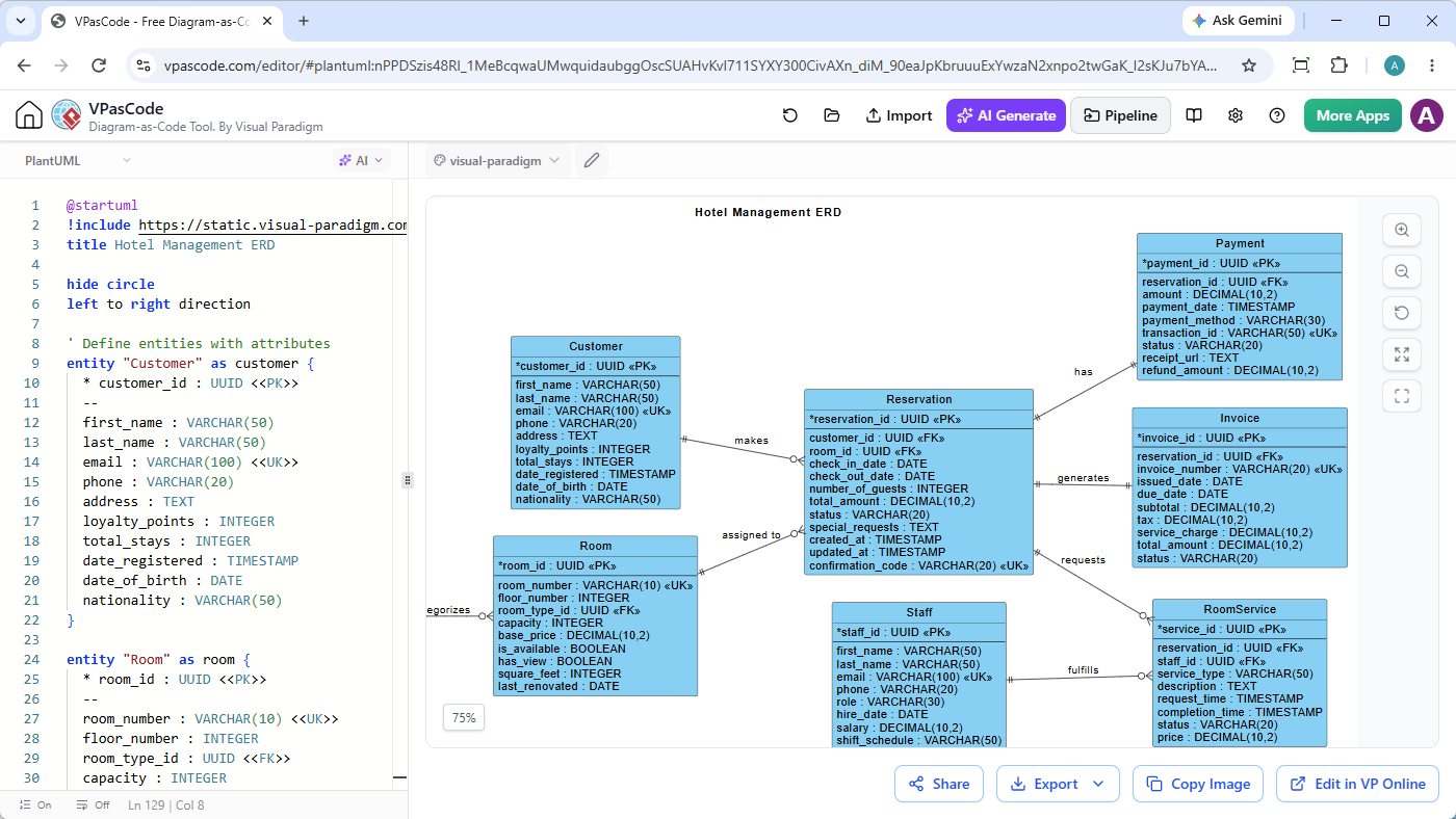
In the world of database design, visualizing complex relationships between data entities is crucial for system architects and developers. While traditional drag-and-drop tools are common, the modern shift towards “Diagram-as-Code” offers unparalleled precision, version control, and automation. This tutorial explores how to leverage VPasCode, Visual Paradigm’s online diagramming platform, to build a robust Entity-Relationship Diagram (ERD) for a Hotel Management System.
We will dissect the architectural logic of the provided code snippet, analyze the resulting database schema, and understand the specific PlantUML syntax used to define constraints, keys, and relationships.
1. The Architecture of “Diagram-as-Code”
The screenshot provided demonstrates a split-screen interface typical of code-based modeling tools. On the left, a raw text editor contains the source code; on the right, the engine renders this text into a semantic visual diagram in real-time. This approach treats the database schema as a source file, allowing teams to use standard version control systems (like Git) to track schema changes.
Why VPasCode?
VPasCode bridges the gap between technical developers and business analysts. It supports multiple formats, but for relational data modeling, it leverages the power of PlantUML. Unlike static images, code-based ERDs are:
- Version Control Friendly: You can see exactly which column was added or which relationship changed via text diffs.
- Template-Ready: Common patterns can be defined once and included in multiple projects.
- AI-Enhanced: Modern versions allow for AI-assisted generation and correction of schema definitions.
2. Analyzing the Schema: Hotel Management Domain
The diagram generated from the code represents a classic hotel reservation system. Let’s break down the entities (tables) and their roles within the system.
Core Entities
- Customer: Stores client information. It includes standard PII (Personally Identifiable Information) like name and email, but also domain-specific attributes like
loyaltypointsanddateregistered. - Room: The physical asset of the hotel. It defines inventory characteristics such as
capacity,floornumber, andbaseprice. - Reservation: The central transactional entity. It links a customer to a room for a specific time period. It also tracks operational details like
checkindateandtotalamount. - Staff: Represents the workforce, including roles and shift schedules.
- Payment: A specialized entity for handling financial transactions, ensuring that payments are linked to specific reservations.
- Invoice & RoomService: Supporting entities for billing and specific service requests (e.g., room service orders).
3. Deep Dive into PlantUML ERD Syntax
The code on the left is written in PlantUML’s ERD syntax. It is declarative, meaning you describe what the data structure is, not how to draw it.
Defining Entities and Attributes
The syntax starts with the entity keyword. Attributes are listed inside the curly braces. The data type is specified after a colon.
entity "Customer" as customer {
    * customer_id : UUID <<PK>>
    --
    first_name : VARCHAR(50)
    last_name : VARCHAR(50)
    email : VARCHAR(100) <<UK>>
    phone : VARCHAR(20)
    address : TEXT
    loyalty_points : INTEGER
    total_stays : INTEGER
    date_registered : TIMESTAMP
    date_of_birth : DATE
    nationality : VARCHAR(50)
}
Key Syntax Elements:
*(Asterisk): Precedes the Primary Key attribute (customerid).<<PK>>: Explicitly tags the attribute as a Primary Key.--: Creates a horizontal separator line in the visual diagram, useful for grouping attributes.<<UK>>: Tags the attribute as a Unique Key (e.g., the email address must be unique).as customer: Defines the alias for the entity, which is used when referencing it in relationships.
Establishing Relationships
Relationships are defined at the end of the code using the relationship keyword. The syntax follows the pattern: EntityA -> EntityB : Description.
relationship "Customer" "makes" "Reservation"
relationship "Reservation" "has" "Payment"
The visual notation in the diagram uses Crow’s Foot notation:
- One-to-Many (1:N): A single
Customer“makes” multipleReservations. - Many-to-One: Multiple
RoomServicerequests “fulfill” a singleReservation(implied by the foreign key logic).
4. Advanced Configuration
The top of the code snippet includes configuration directives that alter how the diagram is rendered.
@startuml
!include https://static.visual-paradigm.com/erd-plantuml.puml
title Hotel Management ERD
hide circle
left to right direction@startuml: Marks the beginning of the PlantUML block.!include: This is critical for VPasCode. It imports a standard library from Visual Paradigm’s servers that defines the ERD-specific syntax and styling rules.hide circle: A styling directive that removes the circular entity-relationship symbols often seen in older diagrams, resulting in a cleaner, more modern look.left to right direction: Forces the layout engine to arrange the boxes horizontally from left to right, rather than the default top-to-bottom flow.
5. Conclusion
The Hotel Management ERD created via VPasCode demonstrates the power of text-based modeling. By defining the schema in code, we ensure that the database design is consistent, documented, and easily modifiable. Whether you are a developer refactoring a legacy system or a data architect designing a new application, mastering this syntax provides a distinct advantage in the software development lifecycle.
Next time you need to model a complex system, consider moving away from the mouse and keyboard and start typing your architecture.