Understanding the static structure of a system is critical for any robust software architecture. While class diagrams provide the blueprint, object diagrams offer a snapshot of reality at a specific moment. This comprehensive guide addresses the most common inquiries regarding UML Object Diagrams, ensuring you have the clarity needed to model instances effectively without the noise of marketing hype.
🔍 What Exactly Is an Object Diagram?
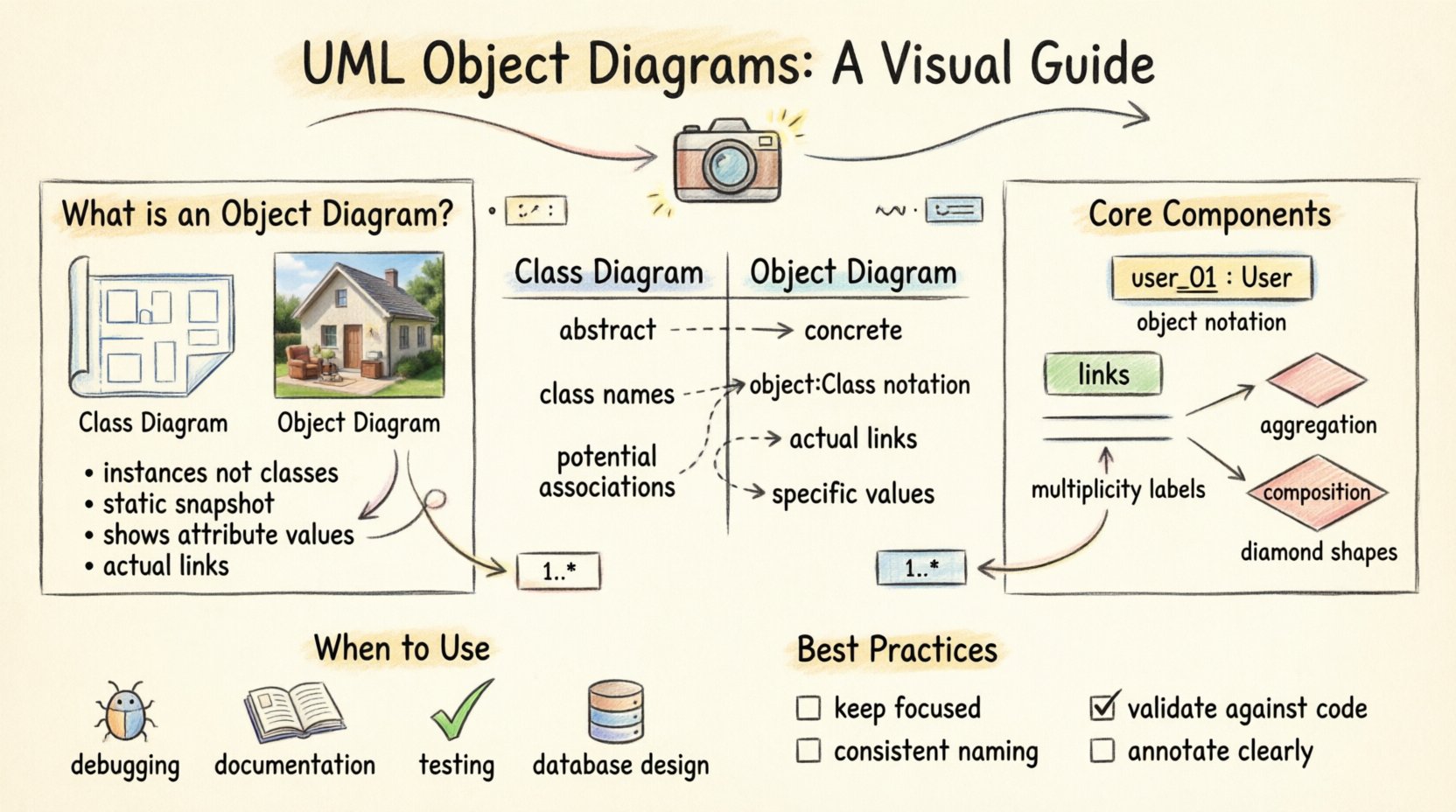
An object diagram is a type of Unified Modeling Language (UML) diagram that shows a complete or partial view of the structure of a modeled system at a specific point in time. Unlike a class diagram, which defines types and relationships generically, an object diagram focuses on instances. It displays specific objects, their attribute values, and the links connecting them.
Think of the class diagram as the architectural blueprint for a house, showing where walls, doors, and windows should go. The object diagram is a photograph of a specific house that has been built, showing exactly which furniture is in the living room and who is currently living in the bedrooms.
Key Characteristics
- Instances over Classes: It represents concrete entities rather than abstract definitions.
- Static Snapshot: It captures the state of the system at a single moment.
- Link Visualization: It highlights the actual connections between objects, not just potential associations.
- Attribute Values: Unlike class diagrams, it often includes specific data values for attributes.
🆚 Object Diagram vs. Class Diagram
Confusion often arises between object diagrams and class diagrams. While they share similar notation, their purpose and content differ significantly. Understanding the distinction is vital for accurate modeling.
| Feature | Class Diagram | Object Diagram |
|---|---|---|
| Focus | Abstract structure and definitions | Concrete instances and states |
| Notation | Class name (e.g., Customer) |
Object name (e.g., customer1 : Customer) |
| Attributes | Attribute names only | Attribute names and specific values |
| Relationships | Potential associations | Actual links existing at runtime |
| Use Case | Design phase, defining structure | Testing, debugging, or documentation |
🧩 Core Components of an Object Diagram
To create a valid and useful diagram, one must understand the fundamental building blocks. These components adhere to the Object Management Group (OMG) specifications.
- Object Instance: Represented as a rectangle with the object name underlined. It typically includes the class name below a separator line. For example,
user_01 : User. - Links: Solid lines connecting object instances. They represent associations that exist between specific objects.
- Multiplicity: The numbers or symbols at the ends of links (e.g., 1, 0..*, 1..1) indicating how many instances can be involved in the relationship.
- State: While primarily static, object diagrams can show the current state of an object’s attributes.
- Ports and Connectors: In complex systems, objects may have ports where interactions occur. Connectors represent the physical or logical wiring between these ports.
❓ Frequently Asked Questions
Below is a detailed breakdown of the most technical and practical questions regarding object diagrams. These answers provide clarity on implementation, design, and usage.
1. How do I represent inheritance in an object diagram?
Inheritance (generalization) is depicted using a solid line with a hollow triangle arrowhead pointing towards the superclass. However, in an object diagram, this relationship is often implicit. If you have an object of type Manager (a subclass), it is inherently an instance of Employee (the superclass). You typically do not draw the inheritance line between the specific instances as frequently as you would in a class diagram, but you must ensure the object’s type reflects the hierarchy.
For example, if manager_01 : Manager exists, it is understood that it also fulfills the requirements of the Employee class structure. The focus remains on the instance’s specific identity and its connections to other instances.
2. Can object diagrams model dynamic behavior?
No, object diagrams are strictly static. They capture a snapshot in time. If you need to model how objects interact over time, change state, or process events, you should utilize Sequence Diagrams, State Machine Diagrams, or Activity Diagrams instead. An object diagram cannot show the flow of messages between objects, only that a link exists between them.
Using an object diagram to imply behavior can lead to misinterpretation by stakeholders. It is a structural artifact, not a behavioral one. If you need to show that an order is being processed, use a sequence diagram to show the message flow. Use the object diagram to show the order object exists and is linked to a customer.
3. What is the difference between an Association and a Link?
This is a fundamental distinction in UML. An Association is a relationship defined in the class diagram. It describes a structural link between two classes. A Link is an instance of that association. It is the actual connection between two specific objects.
In the class diagram, you draw a line labeled knows between Person and Person. In the object diagram, you draw a line labeled knows between alice : Person and bob : Person. The link is the concrete realization of the association.
4. When should I use an object diagram over a class diagram?
Use an object diagram when you need to demonstrate a specific scenario or state. Common use cases include:
- Debugging: Visualizing the state of memory during a crash or error.
- Documentation: Providing a concrete example of how the system looks in practice.
- Testing: Defining expected test data structures.
- Database Design: Showing how data instances relate in a specific query result.
If you are in the early design phase defining the system’s capabilities, a class diagram is more appropriate. If you are verifying the implementation against requirements, an object diagram is more effective.
5. How do I handle multiplicity in object diagrams?
Multiplicity defines how many instances of one class relate to instances of another. In an object diagram, you must respect the multiplicity constraints defined in the class diagram. For example, if a class diagram specifies that one Department can have many Employees, an object diagram showing a department_01 linked to three employee_01, employee_02, and employee_03 instances is valid.
However, you cannot draw a link that violates the constraint. You cannot link a Department object to 100 employees if the constraint is max 50. The diagram must reflect valid data states.
6. Are object diagrams necessary for small projects?
Not necessarily. The overhead of creating object diagrams depends on the complexity of the system. For small scripts or simple applications, the class diagram often suffices to understand the structure. Object diagrams add value when the system has complex relationships or when the specific data state is critical to understanding the business logic.
If your project involves a database with complex foreign key relationships, an object diagram can help visualize the data integrity constraints better than a class diagram alone. If the project is linear, the effort may not yield proportional benefits.
7. How do object diagrams relate to database schemas?
Object diagrams are closely related to database schemas, but they are not identical. A database schema defines the structure (tables, columns, constraints), similar to a class diagram. An object diagram represents the actual data rows and their relationships at a point in time.
When modeling data-intensive applications, an object diagram can serve as a bridge between the logical data model and the physical database. It helps developers see how rows in Table A link to rows in Table B. This is particularly useful for understanding JOIN operations or data migration scenarios.
8. Can I show attributes with values in the diagram?
Yes, this is one of the primary advantages. While class diagrams list attribute names (e.g., age : int), object diagrams can show specific values (e.g., age : 28). This makes the diagram much more descriptive.
However, do not overload the diagram with too much data. If you list every single field for every object, the diagram becomes unreadable. Select the attributes that are relevant to the specific context or question you are trying to answer with the diagram.
9. How do I handle aggregation and composition?
Aggregation and composition are special types of associations representing part-whole relationships. In an object diagram, these are shown using diamond shapes on the line connecting the objects.
- Aggregation: A hollow diamond. It implies a weak relationship where the part can exist independently. For example, a
DepartmenthasEmployees. If the department dissolves, the employees still exist. - Composition: A filled diamond. It implies a strong relationship where the part cannot exist without the whole. For example, a
HousecontainsRooms. If the house is demolished, the rooms cease to exist as parts of that house.
In the object diagram, these relationships indicate the lifecycle dependency between the specific instances shown.
10. What are common mistakes when creating object diagrams?
Several pitfalls can reduce the effectiveness of your modeling:
- Over-complication: Including too many objects makes the diagram cluttered. Focus on the relevant subset.
- Inconsistent Naming: Ensure object names follow a consistent convention (e.g., lowercase with underscores).
- Ignoring Multiplicity: Drawing links that violate the defined cardinality constraints.
- Confusing State and Behavior: Trying to show action flows instead of static states.
- Missing Labels: Forgetting to label the links, which makes the relationship ambiguous.
11. How do I name objects correctly?
The standard convention is objectName : ClassName. The object name should be unique within the diagram. It is often written in lowercase to distinguish it from the class name, which is capitalized. For example, order_55 : Order. This convention helps distinguish between the type (class) and the instance (object) at a glance.
If you have multiple instances of the same class, use a unique identifier. This could be a sequential number, a UUID, or a descriptive label relevant to the business context.
12. Can object diagrams show interface implementation?
Object diagrams can show that an object implements an interface, but it is often redundant if the class structure is already known. If an object user_01 : User implements the interface Authenticatable, you might draw a dashed line with a hollow triangle from the object to the interface, similar to a class diagram. However, the primary focus of the object diagram is usually the instance links, not the interface implementation details.
🛠 Best Practices for Modeling
To ensure your diagrams serve their purpose effectively, adhere to these guidelines.
- Keep it Focused: Do not try to model the entire system in one diagram. Break it down by subsystem, feature, or scenario.
- Use Consistent Notation: Ensure all team members follow the same naming and drawing standards.
- Validate Against Code: Ensure the object diagram matches the actual runtime behavior or data state. It should not be purely theoretical.
- Annotate Clearly: Use text boxes to explain complex relationships or specific constraints that cannot be shown visually.
- Version Control: Treat diagrams as code. Keep them in version control to track changes in the data structure over time.
📉 Analyzing Object Diagrams
Reading an object diagram requires a different mindset than reading code. You are looking for data integrity and relationship validity. When analyzing a diagram, ask:
- Do all links satisfy the multiplicity constraints?
- Are the attribute values within valid ranges?
- Is the object graph connected appropriately, or are there isolated nodes?
- Do the links represent valid business rules?
This analysis is crucial during code reviews or system audits. It helps identify orphaned objects, dangling references, or data inconsistencies that a class diagram might hide.
🚀 Integrating with Other Models
Object diagrams do not exist in isolation. They complement other UML models to provide a complete picture of the system.
- With Class Diagrams: Use the class diagram to define the rules and the object diagram to show the examples.
- With Sequence Diagrams: Use the sequence diagram to show the creation of the objects shown in the object diagram.
- With State Diagrams: Use the state diagram to show how the attributes of the objects change over time.
By integrating these models, you create a cohesive documentation set that addresses structure, behavior, and state simultaneously. This holistic approach reduces ambiguity and ensures that all stakeholders understand the system from multiple perspectives.
📝 Final Thoughts on UML Object Diagrams
Mastery of object diagrams enhances your ability to communicate complex data structures. They provide the necessary detail to validate that the theoretical design aligns with the practical reality of the system. By focusing on instances, links, and states, you gain a deeper insight into the runtime behavior of your software.
Remember that these diagrams are tools for thought and communication. They should clarify complexity, not add to it. When used correctly, they become an indispensable part of the software engineering toolkit, helping teams maintain high-quality architectures and robust data integrity.
As you continue to model your systems, refer back to these questions and guidelines. They serve as a foundation for creating accurate, meaningful, and useful representations of your software’s static structure.