In the landscape of software architecture and system design, clarity is paramount. Among the various modeling techniques available, the Unified Modeling Language (UML) provides a standardized way to visualize system structures. While class diagrams describe the blueprint, object diagrams capture the snapshot. This guide explores the mechanics, syntax, and practical application of UML object diagrams. We will examine how these diagrams function within the broader context of software development and why they remain a critical tool for architects and developers.
What is an UML Object Diagram? 🧩
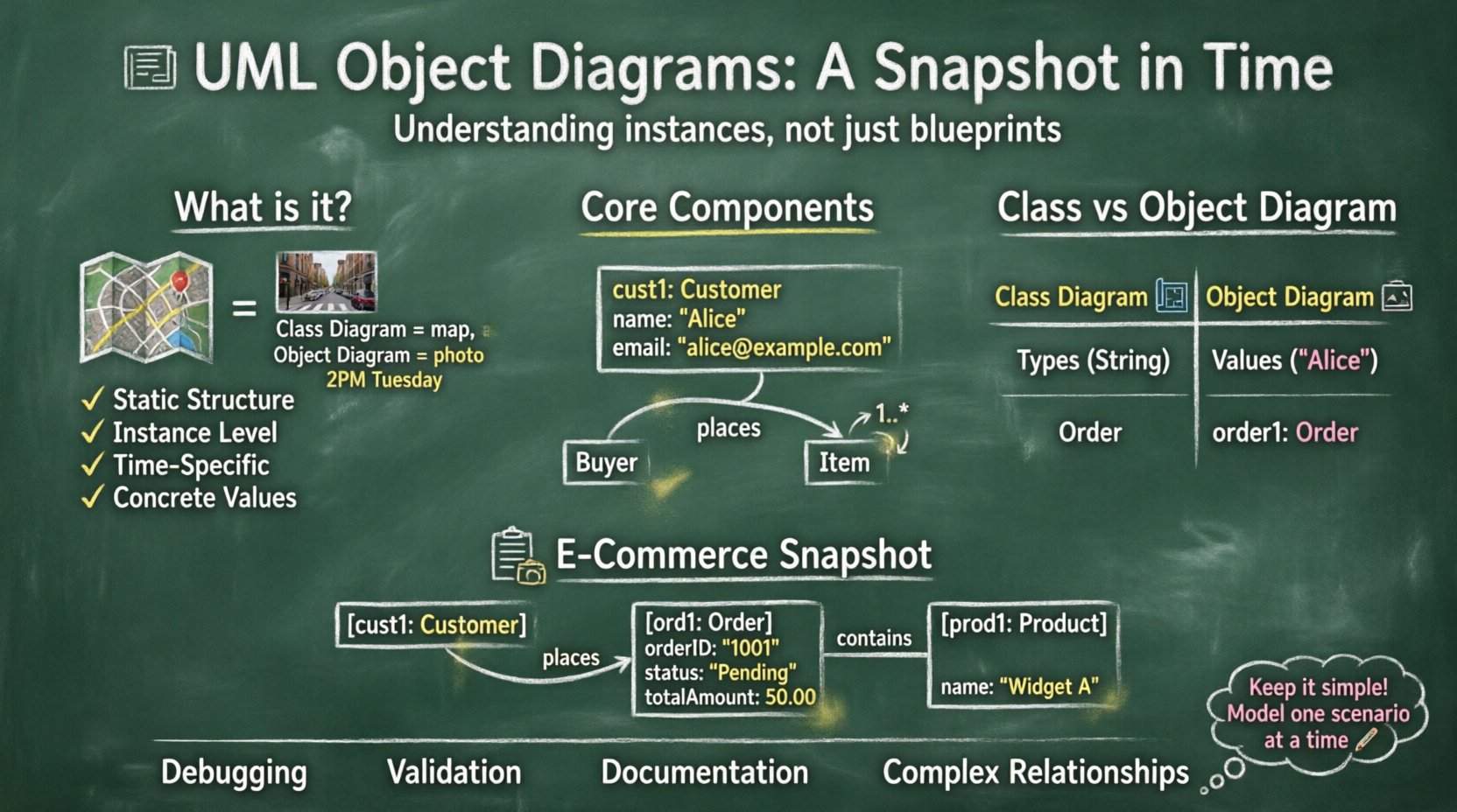
An object diagram is a static structural diagram in UML. It represents a specific instance of a class diagram at a particular point in time. If a class diagram is a map of a city showing all possible roads and buildings, an object diagram is a photograph of a specific street corner at 2:00 PM on a Tuesday. It shows the actual objects that exist, their values, and the links between them.
These diagrams are often referred to as instance diagrams. They serve to validate the design of a system by showing how instances relate to one another. Unlike class diagrams, which focus on types, object diagrams focus on concrete values and specific relationships.
Key Distinctions
- Static Structure: Like class diagrams, object diagrams show structure, not behavior.
- Instance Level: They depict actual instances (objects), not abstract classes.
- Time Specific: They represent a snapshot of the system state.
- Concrete Values: Attributes have actual values, not just types.
Core Components of an Object Diagram 🛠️
To construct a valid object diagram, one must understand the fundamental building blocks. These elements define how objects are represented and how they interact within the model.
1. Objects
An object is a runtime instance of a class. In the diagram, an object is represented by a rectangle. The rectangle is typically divided into two parts:
- Name: The object identifier. It often includes the class name followed by a colon (e.g.,
customer: Customer) or just the instance name (e.g.,cust1: Customer). - Attributes: A list of the object’s properties. Unlike class diagrams, these show the current value (e.g.,
name: "John Doe").
2. Links
Links represent the association between two objects. They are the runtime equivalent of associations in a class diagram. A link connects the specific instances of classes.
- Direction: Links can be unidirectional or bidirectional.
- Role Names: Associations often have role names at the ends of the link to indicate the relationship context.
3. Multiplicity
Multiplicity indicates how many instances of one class relate to an instance of another. In an object diagram, this is often implicit in the number of links drawn, but the constraints are inherited from the class diagram.
- One-to-One: One object links to exactly one other.
- One-to-Many: One object links to many others.
- Many-to-Many: Objects link to multiple instances of the other class.
4. Role Names
Role names clarify the specific function an object plays in an association. For example, in a “Customer buys Product” relationship, the Customer plays the role of “Buyer” and the Product plays the role of “Item”.
Object Diagram vs. Class Diagram 📊
Understanding the difference between these two diagrams is crucial for effective modeling. While they look similar, their purpose and timing differ significantly.
| Feature | Class Diagram | Object Diagram |
|---|---|---|
| Focus | Abstract types and structures | Concrete instances and values |
| Time | Timeless (Blueprint) | Snapshot (Specific moment) |
| Attributes | Data types only (e.g., String) | Actual values (e.g., “Hello”) |
| Usage | Design and development | Documentation and validation |
| Instances | Classes (e.g., Order) |
Objects (e.g., order1) |
When to Use Object Diagrams 🎯
Not every project requires an object diagram. They are specialized tools used in specific scenarios. Knowing when to deploy them saves time and reduces documentation overhead.
- Complex Associations: When relationships between classes are complex, an object diagram helps clarify how instances interact.
- Debugging: Developers can use them to trace the state of a system during a specific execution flow.
- Documentation: For end-users or stakeholders, an object diagram is often easier to understand than a class diagram because it shows real data.
- Validation: Architects use them to verify that the class design supports the required object configurations.
- Database Design: Object diagrams can help visualize how data entities relate in a specific query result.
Constructing an Object Diagram: Step-by-Step 📝
Creating an effective object diagram requires a logical approach. Follow these steps to ensure accuracy and consistency.
- Identify the Scope: Determine which part of the system you are modeling. Do not attempt to model the entire application in one diagram.
- Select the Objects: Choose the specific instances that represent the current state. Pick the active objects relevant to the scenario.
- Define Attributes: Assign concrete values to the attributes of each object. This distinguishes the diagram from a class diagram.
- Draw Links: Connect the objects using association lines. Ensure the links match the multiplicity defined in the class diagram.
- Label Roles: Add role names to the links to explain the nature of the relationship.
- Review Constraints: Check that all constraints (e.g., mandatory links, optional links) are respected in the instance view.
Practical Example: E-Commerce Snapshot 🛒
To illustrate these concepts, consider an e-commerce system. We will model a specific transaction scenario.
Scenario Description
A customer named “Alice” places an order for “Widget A”. The order is pending payment. The system tracks this specific transaction.
Diagram Elements
- Customer Object:
cust1: Customername: "Alice"email: "[email protected]"
- Order Object:
ord1: OrderorderID: "1001"status: "Pending"totalAmount: 50.00
- Product Object:
prod1: Productname: "Widget A"price: 50.00
Relationships
- Customer to Order: Alice (cust1) is linked to Order (ord1). Role:
places. - Order to Product: Order (ord1) contains Product (prod1). Role:
contains.
In this diagram, the values are fixed. The status is “Pending”, not a data type. The name is “Alice”, not a generic string variable. This specificity allows stakeholders to visualize the exact state of the transaction.
Best Practices for Modeling 🏆
Adhering to best practices ensures that diagrams remain useful and readable over time.
1. Naming Conventions
- Use lowercase for object names (e.g.,
cust1) and uppercase for class names (e.g.,Customer). - Prefix the name with the class name to avoid ambiguity (e.g.,
cust1: Customer). - Ensure names are meaningful and reflect the domain.
2. Manage Complexity
- Do not create a single diagram for the entire system. Break it down by subsystem or scenario.
- Focus on the active objects. Objects that are inactive or peripheral can be omitted.
- Use grouping or packaging if the number of objects is large.
3. Consistency with Class Diagrams
- The structure of the object diagram must align with the class diagram. You cannot create a link between two classes if no association exists in the class diagram.
- Multiplicity constraints should be respected.
4. Attribute Values
- Use realistic data types for values. If an attribute is an integer, do not write “ten”; write
10. - For strings, use quotes. For numbers, do not use quotes.
Common Pitfalls to Avoid ⚠️
Even experienced modelers can make mistakes. Being aware of common errors helps maintain diagram quality.
- Over-complication: Trying to model every possible state makes the diagram unreadable. Stick to the relevant scenario.
- Inconsistent Multiplicity: Drawing a one-to-one link when the class diagram specifies one-to-many can cause confusion during implementation.
- Missing Links: Forgetting to draw a link that exists in the class diagram can imply a broken relationship.
- Value Errors: Assigning a value to an attribute that is not of the correct type (e.g., a date string in a number field).
- Ignoring State: Failing to represent the current state of the object can lead to incorrect assumptions about system behavior.
Integration with Other UML Diagrams 🔗
Object diagrams do not exist in isolation. They interact with other diagrams to provide a complete picture of the system.
Sequence Diagrams
Sequence diagrams show the flow of messages over time. Object diagrams provide the static context for these interactions. An object in a sequence diagram corresponds to a lifeline, which is an instance of a class, matching the object diagram.
State Machine Diagrams
State diagrams show how an object changes state. Object diagrams show the state of objects at a specific moment. They complement each other by showing the “when” and the “what”.
Activity Diagrams
Activity diagrams describe the workflow. Object diagrams can be used to show the inputs and outputs (objects) of specific activities within the workflow.
Maintenance and Evolution 🔄
Software is dynamic. Diagrams must evolve with the code. However, maintaining object diagrams is often more challenging than class diagrams because they represent specific states.
Updating Diagrams
- Version Control: Treat diagrams as code. Store them in version control systems.
- Regular Reviews: Review diagrams during sprint planning or design reviews to ensure they match the current implementation.
- Automation: Where possible, generate diagrams from code to reduce manual maintenance, though this is not always feasible for specific instance scenarios.
Documentation Strategy
Object diagrams are excellent for documentation but can become outdated quickly. It is often better to use them for:
- Onboarding new developers to the data model.
- Explaining complex business rules involving multiple entities.
- Debugging specific issues in production environments.
Technical Syntax Details 🖊️
Understanding the visual syntax is essential for creating standard-compliant diagrams.
Object Rectangles
The object rectangle is divided into two compartments. The top compartment contains the object name. The bottom compartment contains the attributes. If the object has no attributes, the bottom compartment can be omitted.
Link Lines
Links are drawn as straight lines. They can be labeled with the association name. Role names are placed at the ends of the line. Multiplicity is usually shown on the class diagram but can be reiterated on the object diagram if necessary for clarity.
Navigation
Links can be navigable or non-navigable. In an object diagram, this is often implied by the direction of the link arrow. If a link is bidirectional, no arrow is used. If unidirectional, an arrow points to the target.
Conclusion on Modeling Strategy 🧠
UML object diagrams are a specialized but powerful tool in the software engineering toolkit. They bridge the gap between abstract design and concrete implementation. By focusing on instances rather than types, they provide a clear view of system state at a specific moment. While they require careful maintenance, their value in communication, validation, and documentation is significant. When used correctly, they reduce ambiguity and help teams build more robust systems.
Remember that diagrams are communication tools, not just documentation. Their primary goal is to facilitate understanding among stakeholders. Keep them simple, accurate, and relevant to the current development phase. Avoid over-engineering the visual representation, and focus on the information that drives design decisions.