Timing diagrams serve as the blueprint for signal behavior in digital systems. They map out voltage levels, transitions, and temporal relationships between various signals. Without these visualizations, verifying the correctness of a design is nearly impossible. Engineers use them to ensure data arrives at the right time and state.
1. What exactly is a timing diagram? 🤔
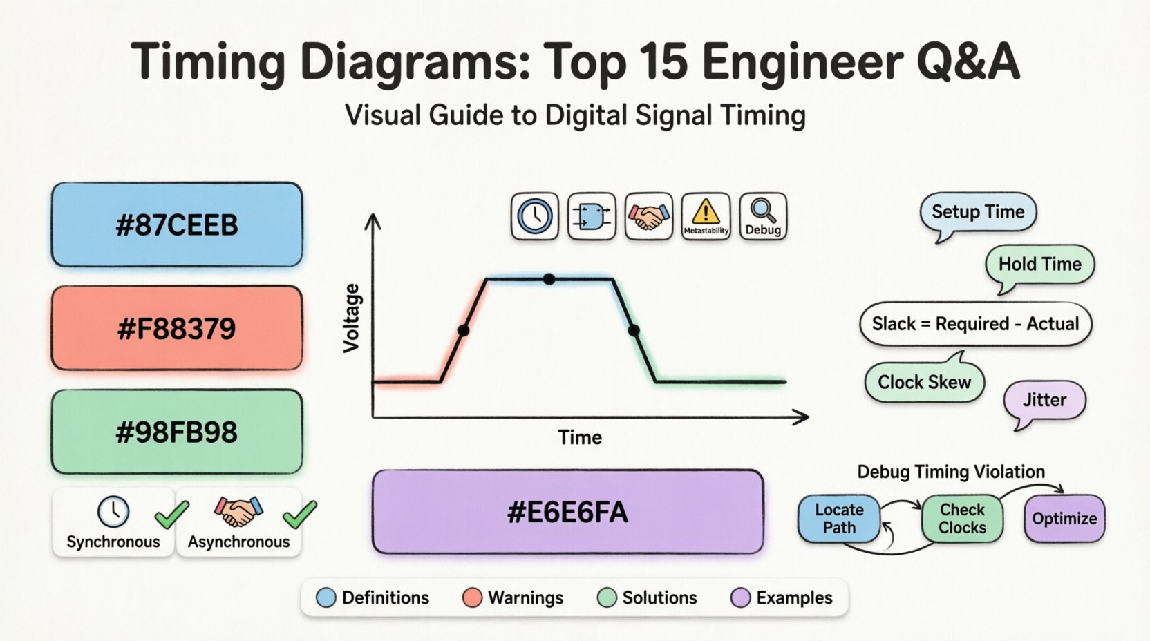
A timing diagram is a graphical representation that shows the relationship between two or more signals over a period of time. It plots time on the horizontal axis and signal voltage levels on the vertical axis.
- Time Axis: Represents the progression of events.
- Signal Axis: Represents logic levels (High, Low, or High-Z).
- Events: Show transitions like rising edges, falling edges, and hold states.
This tool allows designers to visualize clock cycles, data windows, and control signals simultaneously.
2. Why are timing diagrams critical in digital design? ⚙️
Digital systems rely on precise synchronization. If signals do not align correctly, data corruption occurs. Timing diagrams highlight these alignment issues before hardware is fabricated.
- Validation: They confirm if logic meets specifications.
- Debugging: They help locate where a signal deviates from expectations.
- Communication: They provide a common language between hardware and software teams.
Skipping this step often leads to functional failures in the field.
3. What is the difference between setup time and hold time? ⏳
These are two fundamental constraints for flip-flops and registers. They define the safe window for capturing data.
- Setup Time: The minimum time data must be stable before the clock edge arrives.
- Hold Time: The minimum time data must remain stable after the clock edge arrives.
Violating setup time causes the next cycle to capture wrong data. Violating hold time prevents the current data from latching correctly.
4. How do you calculate setup slack? 📐
Slack is the margin of error available in a timing path. It determines if a path is too fast or too slow.
| Parameter | Description |
|---|---|
| Required Time | When the data must arrive at the destination. |
| Actual Time | When the data actually arrives based on propagation delay. |
| Slack | Required Time minus Actual Time. |
A positive slack indicates a safe path. Negative slack indicates a violation that must be fixed.
5. What is clock skew and why does it matter? 🕒
Clock skew occurs when the clock signal arrives at different components at different times. This happens due to path length differences or load variations.
- Negative Skew: The capture clock arrives earlier than the launch clock.
- Positive Skew: The capture clock arrives later than the launch clock.
Skew can effectively increase setup time or reduce hold time requirements, impacting the maximum frequency of the system.
6. How do you identify metastability in a diagram? 🌪️
Metastability happens when a signal is sampled during a transition, leaving the output in an undefined state. In a timing diagram, this looks like a signal that does not settle to a valid High or Low level within the expected clock cycle.
- Visual Cue: A waveform that remains in the middle voltage region.
- Consequence: It can propagate errors through the logic chain.
Engineers use synchronizers to mitigate the risk of metastability entering the core logic.
7. What is the difference between synchronous and asynchronous timing? 🔄
The distinction lies in how signals are coordinated across the system.
| Feature | Synchronous | Asynchronous |
|---|---|---|
| Clock | Shared global clock. | No global clock; uses handshakes. |
| Prediction | Easy to predict timing. | Harder to predict; dependent on data. |
| Complexity | Standard logic design. | Requires FIFOs or handshake protocols. |
Synchronous designs are easier to analyze with static timing analysis tools. Asynchronous designs offer speed benefits but require rigorous verification.
8. Why are rise and fall times important? 📈
These parameters measure how quickly a signal transitions between logic levels. Ideally, transitions should be instantaneous, but physical limitations cause slopes.
- Slow Rise: Can cause the signal to be interpreted as intermediate logic levels.
- Fast Fall: Can introduce noise or crosstalk.
If the transition is too slow, it may violate setup or hold times. If too fast, it increases electromagnetic interference.
9. What is propagation delay? ⏱️
Propagation delay is the time it takes for a signal to travel from the input of a component to its output. It is inherent to the physical gates and interconnects.
- Logic Delay: Time taken by the gate to switch.
- Wire Delay: Time taken for the signal to traverse the trace.
This value accumulates across a chain of logic gates. Designers must sum these delays to ensure data meets the destination within one clock cycle.
10. How does duty cycle affect timing? 🔁
Duty cycle defines the percentage of time a signal stays High versus Low within one period. A 50% duty cycle is standard, but deviations occur.
- Narrow Pulse: If the clock pulse is too narrow, setup time requirements might not be met.
- Wide Pulse: Excessive High time can cause hold time violations in certain latch designs.
Consistency in duty cycle ensures stable operation across varying temperatures and voltages.
11. What is jitter and how does it impact signals? 📉
Jitter is the deviation of a signal’s timing from its ideal position. It is noise on the clock or data lines.
- Period Jitter: Variation in the time between clock edges.
- Phase Jitter: Variation in the phase of the clock relative to a reference.
Jitter reduces the timing margin available for setup and hold checks. Excessive jitter can lead to data errors even if the design is theoretically sound.
12. When do you use multi-cycle paths? 🛤️
Multi-cycle paths are used when a signal requires more than one clock cycle to propagate from source to destination. This often happens in complex arithmetic operations.
- Use Case: Complex multipliers or dividers.
- Constraint: The timing tool must be told to ignore intermediate cycles.
Without this constraint, the tool might flag the path as a violation because it expects data to arrive in one cycle.
13. How do you debug a timing violation? 🔍
Debugging involves identifying the specific path causing the failure and analyzing the root cause.
- Locate the Path: Check the report for the violating path.
- Analyze Delays: Look at logic depth and wire length.
- Check Clocks: Verify clock frequencies and skew.
- Optimize: Pipeline the logic or increase clock frequency.
Tools often highlight the longest paths automatically to assist in this process.
14. What is a false path? ❌
A false path is a signal route that never actually carries data in the functional operation of the circuit. However, the timing tool might still analyze it.
- Example: Control logic that is never enabled simultaneously with data logic.
- Action: Mark it as a false path in the constraints file.
Ignoring false paths prevents unnecessary optimization and reduces analysis time.
15. How do asynchronous clock domains interact? 🌍
When two parts of a system run on different clocks, data transfer is risky. The clocks might drift or skew unpredictably.
- Risk: Sampling data during a transition between domains.
- Solution: Use FIFO buffers or handshake protocols.
A timing diagram for asynchronous domains must explicitly show the handshaking signals (Valid, Ready) to ensure data safety.