Designing systems where timing is paramount requires a disciplined approach. Whether developing safety-critical automotive control units, aerospace avionics, or industrial automation controllers, the predictability of execution is non-negotiable. Time-triggered behavior is a fundamental architectural pattern used to ensure that system actions occur at precise intervals, regardless of external interruptions. This guide provides a deep dive into the methodology of modeling this behavior using timing diagrams.
We will explore the theoretical underpinnings, the practical steps for construction, and the rigorous verification required to ensure reliability. By the end of this walkthrough, you will understand how to translate abstract temporal requirements into concrete, visual specifications that drive robust system design. 🛠️
🔍 Understanding Time-Triggered Architectures
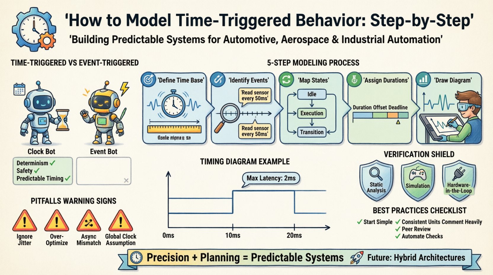
Before diving into the modeling process, it is essential to grasp the distinction between time-triggered and event-triggered systems. In an event-triggered system, a component acts only when a specific stimulus occurs. This is efficient but can lead to unpredictable latencies under high load. Conversely, time-triggered systems operate on a global or local clock. Actions are scheduled to happen at predetermined moments.
- Determinism: The primary advantage. You know exactly when a task will run.
- Safety: Easier to prove that deadlines are met in safety-critical contexts.
- Complexity: Requires careful synchronization across distributed nodes.
When modeling this behavior, we rely on timing diagrams. These visual tools map the relationship between signals, states, and time. They serve as the blueprint for both software developers and hardware engineers. 📊
📋 Prerequisites for Effective Modeling
Jumping straight into drawing a diagram without a clear foundation often leads to errors. Proper preparation ensures that the model reflects the actual physical and logical constraints of the system. You must gather specific inputs before beginning the modeling process.
1. Requirements Specification
Every timing constraint originates from a requirement. Is there a maximum latency allowed for a sensor reading? Is there a minimum frequency for a control loop? These values must be documented clearly. Ambiguity here is the enemy of precision.
2. Hardware Constraints
The physical environment dictates the limits of your model. What is the clock speed of the microcontroller? How much jitter exists in the communication bus? These hardware realities must be factored into the timing margins. 🖥️
3. Inter-Component Dependencies
Systems rarely exist in isolation. A motor controller depends on the brake system, which depends on the sensor array. Understanding the data flow and dependencies is crucial for mapping the correct sequence of events.
⚙️ Step-by-Step Modeling Process
Constructing a time-triggered model is a methodical exercise. It involves breaking down the system behavior into granular time units and assigning logic to those units. Follow this structured approach to ensure accuracy.
Step 1: Define the Time Base
The foundation of any timing diagram is the time axis. You must establish a reference clock. This is often referred to as the “system tick” or “cycle time”.
- Choose a Granularity: Will you model in milliseconds, microseconds, or clock cycles? Choose the smallest unit necessary to capture critical behavior.
- Set the Period: Determine the fundamental period of the system. For example, if a control loop runs every 10 milliseconds, your base period should be 10ms or a divisor of it.
- Mark the Ticks: Visually or logically mark the start of each cycle. These are the moments where time-triggered actions are eligible to fire.
Step 2: Identify Time-Triggered Events
Not every action in a system is time-triggered. You need to distinguish between events that happen because of time and events that happen because of state changes. Isolate the actions that must occur at specific intervals.
| Event Type | Trigger Condition | Example |
|---|---|---|
| Time-Triggered | Specific Time/Cycle | Read sensor every 50ms |
| Event-Triggered | Signal Change | Alert when temperature > 100°C |
| Hybrid | Time + Event | Send data if time is 100ms AND buffer is full |
Focus your modeling efforts primarily on the Time-Triggered column. These are the predictable anchors of your design.
Step 3: Map State Transitions
Once the time base is set and the events are identified, you must define the states the system occupies during these intervals. A state machine is often the underlying logic.
- Idle State: What does the system do when waiting for the next trigger? Does it consume power? Does it poll inputs?
- Execution State: The specific actions taken when the timer fires. This includes calculation, communication, or actuation.
- Transition Logic: Define the conditions required to move between states. While time triggers the entry, state logic determines the exit.
Ensure that state transitions are mutually exclusive where possible to prevent race conditions. ⚡
Step 4: Assign Durations and Offsets
Knowing when a task starts is only half the battle. You must also define how long it lasts and any offsets relative to the start of the cycle.
- Duration: Estimate the execution time. Include worst-case execution time (WCET) to ensure safety margins.
- Offset: Does the task start immediately at the cycle start (offset 0), or is there a delay? For example, a sensor read might start at 5ms into a 10ms cycle to allow the previous task to finish.
- Deadlines: When must the output be ready? This defines the end of the task window.
Step 5: Draw the Timing Diagram
This is the visualization phase. Use standard notation to represent the data you have collected. A timing diagram typically has time on the horizontal axis and signals or states on the vertical axis.
- Draw the Time Axis: Label intervals clearly (e.g., 0ms, 10ms, 20ms).
- Plot Signals: Draw horizontal lines for high/low states or vertical spikes for pulses.
- Add Annotations: Use arrows or text to indicate specific constraints, such as “Max Latency: 2ms”.
- Highlight Cycles: Visually group segments that represent one full period of the time base.
📐 Timing Diagram Notation Standards
To ensure your model is understood by other engineers, adhere to established notation conventions. While specific styles may vary, the core principles remain consistent.
- Signal Lines: Horizontal lines represent the state of a signal over time. Vertical lines represent instantaneous transitions.
- High/Low States: Clearly define what logic level 1 and 0 represent physically (e.g., 3.3V vs 0V).
- Delays: Use brackets or specific symbols to denote latency between input and output.
- Parallelism: Use stacked signals to show concurrent activities. If two tasks run simultaneously, their time blocks should align horizontally.
Clarity is paramount. If a colleague cannot read your diagram within five minutes, it needs refinement. 👁️
🛡️ Verification and Validation
Modeling is not complete until the design has been verified. This step ensures that the theoretical model matches the intended requirements and can withstand real-world conditions.
1. Static Analysis
Review the model for logical consistency. Are there any time windows where two tasks conflict? Is the bus bandwidth sufficient for the scheduled data transfers? Static analysis tools can often detect these conflicts automatically.
2. Simulation
Run a virtual execution of the model. Feed it test cases that simulate normal operation and edge cases (e.g., signal loss, network delay). Observe if the timing constraints are violated.
- Stress Testing: Push the system to its limits. What happens if the clock jitter increases?
- Boundary Testing: Test at the exact edges of your defined time windows.
3. Hardware-in-the-Loop (HIL)
Where possible, connect the model to actual hardware. This captures the real-world electrical noise and processing delays that a pure software model might miss. 🖧
⚠️ Common Pitfalls in Time-Triggered Modeling
Even experienced engineers encounter specific challenges when working with time-triggered systems. Being aware of these common issues can save significant debugging time.
1. Ignoring Jitter
Real clocks are not perfect. They drift and jitter. If you model a perfect 10ms cycle, your system will fail when the clock varies by 1%. Always include a jitter buffer in your timing margins.
2. Over-Optimization
Trying to fit every task into the tightest possible window can make the system brittle. Leave slack time for unexpected events or priority interrupts. A robust system is better than a perfectly optimized one. ⚖️
3. Asynchronous Mismatches
Time-triggered systems often interface with event-triggered peripherals. For example, a keyboard input is event-triggered, but the system polls it on a time trigger. If the polling rate is too slow, inputs are missed. If too fast, resources are wasted.
4. Global Clock Assumptions
In distributed systems, assuming all nodes share a perfectly synchronized clock is dangerous. Network latency and clock drift must be accounted for using synchronization protocols.
🔄 Maintenance and Evolution
A timing diagram is not a one-time artifact. As requirements change, the model must evolve. This section outlines how to maintain the integrity of your time-triggered model over the lifecycle of the project.
Version Control
Treat your timing diagrams as code. Use version control systems to track changes. This allows you to revert to previous versions if a new change introduces timing violations.
Change Impact Analysis
Before modifying a time constraint, perform an impact analysis. Changing a cycle time from 10ms to 5ms doubles the CPU load and halves the available time for other tasks. Document the ripple effects of any change.
Documentation Updates
Keep the textual requirements aligned with the visual model. If the diagram changes, the requirements document must be updated immediately. Discrepancies between text and diagram lead to implementation errors. 📝
📊 Comparing Modeling Approaches
While time-triggered modeling is the focus here, it is useful to compare it briefly with other modeling styles to understand its specific niche.
| Approach | Primary Focus | Best Used For |
|---|---|---|
| Time-Triggered | Predictable Latency | Safety-critical control loops |
| Event-Triggered | Responsiveness | User interfaces, background tasks |
| Data-Flow | Throughput | Signal processing pipelines |
Understanding where time-triggered modeling fits within this landscape helps in selecting the right tools and techniques for the job.
🎯 Best Practices for Success
To ensure your time-triggered behavior models are robust and maintainable, follow these established best practices.
- Start Simple: Model the core loop first. Add complexity and peripheral tasks only after the main timing is verified.
- Use Consistent Units: Stick to milliseconds or microseconds throughout the entire project. Mixing units leads to calculation errors.
- Comment Heavily: Annotate every significant timing decision. Explain why a 5ms offset was chosen, not just that it was chosen.
- Review Regularly: Conduct peer reviews of the timing diagrams. A second pair of eyes often catches a missed deadline or a race condition.
- Automate Checks: Where possible, use scripts to validate timing constraints against the model. This reduces human error.
🔮 The Future of Timing Models
As embedded systems become more complex, the demand for precise timing models increases. Modern systems often combine time-triggered and event-triggered paradigms in a hybrid architecture. This requires even more sophisticated modeling techniques.
Future advancements may include automated generation of timing diagrams from high-level code, reducing the manual effort required. However, the fundamental need for human oversight and logical validation remains constant. Engineers who understand the underlying principles of time-triggered behavior will remain essential. 🚀
📝 Summary of Key Takeaways
Modeling time-triggered behavior is a critical skill for ensuring system reliability. By establishing a clear time base, identifying specific triggers, mapping states, and rigorously verifying the design, you create a foundation for predictable system performance. Remember that timing is not just about speed; it is about order and certainty.
Key points to remember:
- Establish a precise time base and cycle period.
- Distinguish between time-triggered and event-triggered actions.
- Use standard timing diagram notation for clarity.
- Account for hardware jitter and execution variability.
- Maintain the model throughout the system lifecycle.
With discipline and attention to detail, you can build systems that operate with the precision required by modern technology. The path to reliability is paved with accurate timing models. ⏱️