


Understanding the architecture of a software system requires precise documentation. Unified Modeling Language (UML) provides the standard vocabulary for this purpose. Within this framework, two specific diagram types often cause confusion among developers and architects: the UML Object Diagram and the UML Class Diagram. While they share visual similarities, their purposes, levels of abstraction, and utility in the development lifecycle differ significantly.
This guide explores the structural nuances, practical applications, and technical distinctions between these two modeling artifacts. By grasping the specific use cases for each, teams can ensure their system design documents remain clear, accurate, and valuable throughout the project lifecycle.
What is a UML Class Diagram? 📊
The Class Diagram is the backbone of object-oriented system design. It describes the static structure of a system by showing its classes, attributes, operations, and the relationships among objects. It acts as a blueprint, defining what can exist in the system rather than what is currently existing.
Core Components
- Class: Represented as a rectangle divided into three compartments. The top holds the class name, the middle lists attributes, and the bottom lists operations (methods).
- Attributes: Properties that define the state of an instance. Visibility modifiers (e.g.,
+for public,-for private) precede the attribute name. - Operations: Behaviors or methods available to the class. They follow the same visibility rules as attributes.
- Multiplicity: Defines how many instances of a class can be associated with another. Common notations include
1,0..1,1..*, and*.
Key Characteristics
- Static Nature: Class diagrams represent the static structure. They do not show the dynamic flow of data or the sequence of events.
- Generalization: They focus on the general definition of types, not specific instances. A
Customerclass defines the rules for any customer, not a specific person named “John”. - Design Phase: Typically created during the design phase to establish the schema and logic before coding begins.
When creating a Class Diagram, the focus is on reusability and scalability. It defines the contract that the code must adhere to. If the Class Diagram changes, the underlying code structure often requires a refactor.
What is a UML Object Diagram? 🖼️
An Object Diagram is a snapshot of the system at a specific point in time. It shows instances of classes, their specific values, and the links between those instances. If a Class Diagram is the blueprint, an Object Diagram is a photograph of the building under construction.
Core Components
- Object Instance: Represented similarly to a class but with an underline in the name. The name often follows the pattern
objectName : ClassName. - Attribute Values: Unlike the Class Diagram which lists attribute types, the Object Diagram lists the actual values assigned to those attributes at that moment.
- Links: Represent specific associations between instances. A link is an instance of an association defined in the Class Diagram.
Key Characteristics
- Dynamic Snapshot: It captures the runtime state. It answers the question, “What does the data look like right now?”
- Concrete Data: It deals with concrete instances. It validates whether the relationships defined in the Class Diagram can actually hold real-world data.
- Debugging & Testing: Often used to verify complex associations or to debug memory states during the testing phase.
Object diagrams are less common than class diagrams in high-level architectural discussions. They are more specialized, used when the specific configuration of data instances is critical to understanding the behavior of the system.
Key Differences at a Glance 🧐
To visualize the structural and functional distinctions, consider the following comparison table. This highlights the divergence in purpose, notation, and lifecycle stage.
| Feature | UML Class Diagram | UML Object Diagram |
|---|---|---|
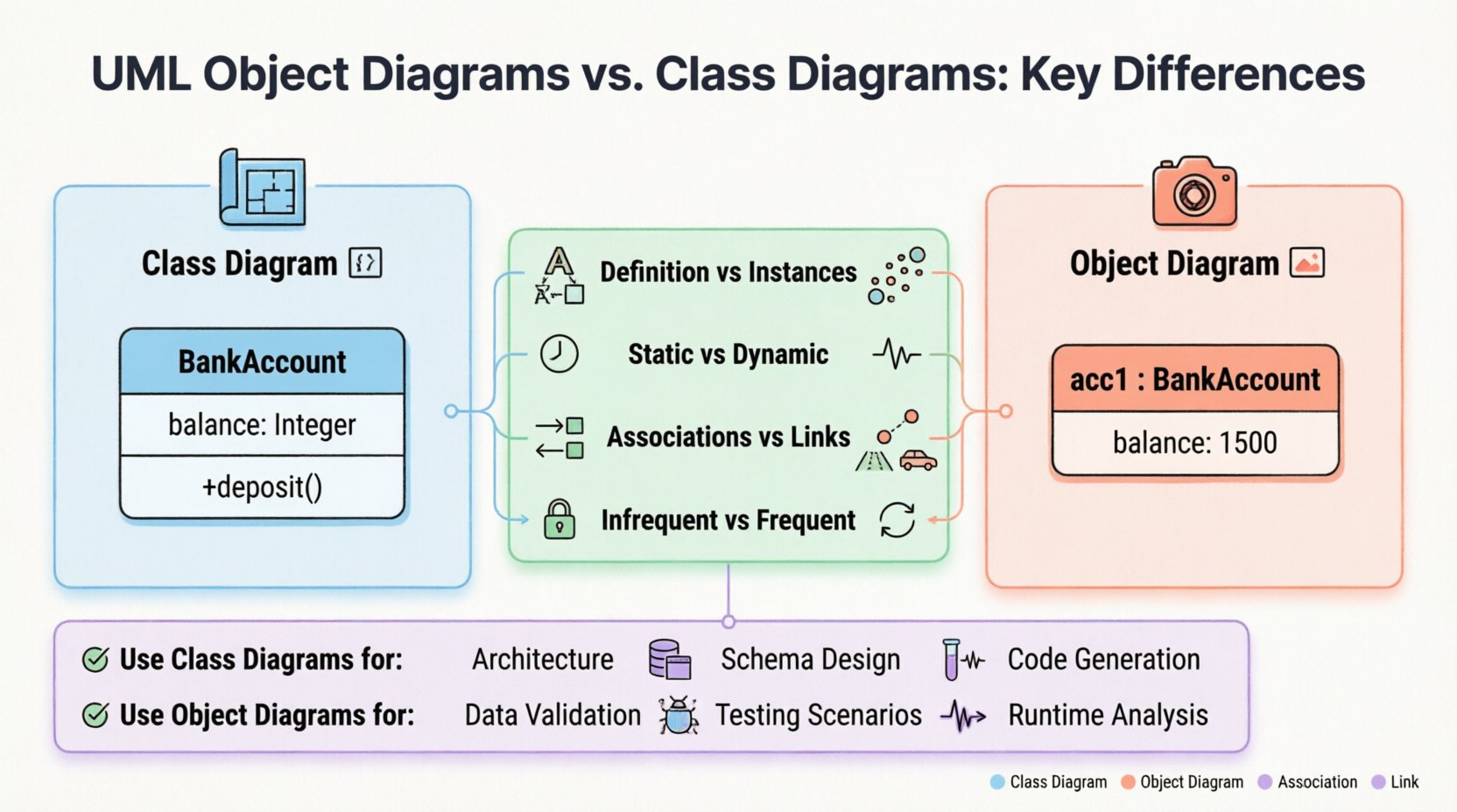
| Focus | Definition and Structure | Instances and State |
| Abstraction Level | High (Type Level) | Low (Instance Level) |
| Time Context | Static (Blueprint) | Dynamic (Snapshot) |
| Attribute Display | Attribute Name + Type | Attribute Name + Value |
| Relationships | Associations | Links |
| Primary Use Case | Design and Architecture | Validation and Debugging |
| Frequency of Update | Infrequent (Stable) | Frequent (Volatile) |
When to Use Which? 🤔
Choosing between these diagrams depends on the goal of the documentation. Using the wrong diagram can lead to confusion or incomplete understanding of the system.
Use Class Diagrams For:
- System Architecture: When defining the overall structure of the software.
- Database Schema Design: Mapping classes to tables and defining constraints.
- Interface Definition: Establishing how different modules will interact.
- Code Generation: Many tools can generate skeleton code directly from Class Diagrams.
- Long-term Documentation: Since the structure rarely changes as drastically as the data, class diagrams remain valid longer.
Use Object Diagrams For:
- Complex Associations: When a many-to-many relationship has specific constraints that are hard to express in text.
- Data Validation: Checking if a specific set of data can exist within the defined structure.
- Testing Scenarios: Defining the exact state of objects required to trigger a specific test case.
- Runtime Analysis: Debugging memory leaks or understanding object lifecycles during execution.
- Documentation of Specific Cases: Explaining a bug report that involves a specific configuration of objects.
Deep Dive: Structure and Syntax 🔧
While the visual elements look similar, the syntax rules enforce the difference in meaning. Adhering to these conventions prevents ambiguity.
Class Naming Conventions
- Class Diagram: Use PascalCase (e.g.,
BankAccount). This signifies a type. - Object Diagram: Use lowercase for the instance name, followed by a colon and the Class name (e.g.,
acc1 : BankAccount). This signifies an instance.
Attribute Representation
- Class Diagram: Lists the data type.
balance : Integer. - Object Diagram: Lists the actual value.
balance : 1500.
This distinction is critical. In a Class Diagram, you cannot define the value of an attribute because the class might be instantiated with any valid integer. In an Object Diagram, the value is fixed for that specific snapshot.
Multiplicity and Cardinality
Both diagrams use multiplicity, but the interpretation shifts.
- Class Diagram: Defines the rule. “One Customer can have zero or more Orders” (
0..*). - Object Diagram: Shows the reality. In this specific snapshot, Customer A has exactly three Order objects linked to it.
Relationship Mapping 🕸️
Relationships are the glue that holds the system together. Understanding how they translate between Class and Object diagrams is vital for accurate modeling.
Associations vs. Links
- Association: A structural relationship between classes. It is defined in the Class Diagram. It represents the potential for a connection.
- Link: A connection between instances. It is defined in the Object Diagram. It represents an actual connection.
Think of an Association as a road on a map and a Link as a car driving on that road. The road exists regardless of traffic; the car exists only when it is there.
Aggregation and Composition
These relationships denote ownership and lifecycle dependencies.
- Aggregation: A “has-a” relationship where the parts can exist independently. In an Object Diagram, this is shown as a link where the object instance might be shared.
- Composition: A strong “part-of” relationship. If the whole dies, the parts die. In an Object Diagram, this implies a tighter binding between the specific instances.
Common Pitfalls and Best Practices ⚠️
Mistakes in modeling can lead to implementation errors. Here are common issues to avoid.
Pitfall: Overloading Object Diagrams
Do not create Object Diagrams for every possible state. They become unreadable quickly if too many instances are shown. Use them only to illustrate specific, complex scenarios.
Pitfall: Confusing Types with Instances
Never mix Class and Object notations in the same diagram unless explicitly labeling them as such. It creates ambiguity for the reader. If you see an instance name, it must be an Object Diagram.
Best Practice: Consistency
- Ensure the Object Diagram aligns perfectly with the Class Diagram. If the Class Diagram says a relationship is optional, the Object Diagram should not force it.
- Use consistent naming conventions across all diagrams in the project.
Best Practice: Clarity
- Use color or shape variations only if they convey semantic meaning, not just for aesthetics.
- Keep the scope of the Object Diagram narrow. Focus on the specific objects involved in the scenario being discussed.
Real-world Application Scenarios 🏗️
How do these diagrams function in actual development workflows?
Scenario 1: E-Commerce Platform Design
During the design phase, the team creates a Class Diagram to define Product, Cart, and Order. They define that a Cart contains multiple Products. This sets the rules.
Later, during a code review, a developer notices a potential memory leak when a Cart is closed. They create an Object Diagram to trace the specific instances of Cart and Product objects in memory. This helps visualize the lifecycle issue.
Scenario 2: Database Migration
When migrating data to a new schema, the Class Diagram is updated to reflect the new table structure. The Object Diagram is used to generate test data sets. It ensures that the test data respects the constraints of the new schema.
Scenario 3: API Documentation
API documentation often relies on Class Diagrams to show request/response structures. However, for complex nested responses, an Object Diagram can show a specific example payload, making it easier for frontend developers to understand the data structure.
Maintenance and Evolution 🔄
Models are not static documents; they evolve with the software.
Class Diagram Maintenance
- Updated when the architecture changes.
- Updated when new features require new classes.
- Considered the source of truth for the system structure.
Object Diagram Maintenance
- Updated only when specific scenarios change significantly.
- Often discarded after the specific debugging or documentation task is complete.
- Less likely to be version-controlled unless it serves as a critical test case definition.
Integration with Other UML Diagrams 🔗
UML is a suite of tools. Class and Object diagrams do not exist in isolation.
Sequence Diagrams
Sequence diagrams show the flow of messages. They reference the classes defined in the Class Diagram. Sometimes, they implicitly reference Object Diagrams when showing specific object interactions.
State Machine Diagrams
State machines describe the lifecycle of an object. They rely heavily on the definition of the Class Diagram. The states and transitions are attached to specific classes.
Component Diagrams
Component diagrams group classes into modules. The Class Diagram provides the detailed structure inside the components. The Object Diagram can show the instantiation of components within a runtime environment.
Summary of Findings 📝
Selecting the right diagram type is a decision based on the stage of development and the information required.
- Class Diagrams are the structural foundation. They define the rules, types, and static relationships. They are essential for design, coding, and long-term documentation.
- Object Diagrams are the runtime verification. They show specific instances and data states. They are essential for debugging, testing, and explaining complex configurations.
By distinguishing between the blueprint (Class) and the snapshot (Object), teams can maintain a clear separation between design intent and runtime reality. This clarity reduces errors, improves communication, and ensures that the system remains robust throughout its lifecycle.
Adopting these practices leads to better system design and more maintainable codebases. Focus on the static structure with Class Diagrams, and use Object Diagrams when the specific state of the data matters.