


UML Object Diagrams provide a static snapshot of a system at a specific point in time. They illustrate instances of classes and the relationships between those instances. While they are powerful for visualizing data states, creating and maintaining them often leads to structural inconsistencies and logical errors. This guide addresses frequent pitfalls found during the design and validation of object diagrams, offering a clear path to resolution.
When working with object diagrams, precision is paramount. A single misplaced link or incorrect multiplicity can invalidate the entire model. The following sections break down the most common technical challenges, providing actionable steps to identify and correct them without relying on specific commercial tools.
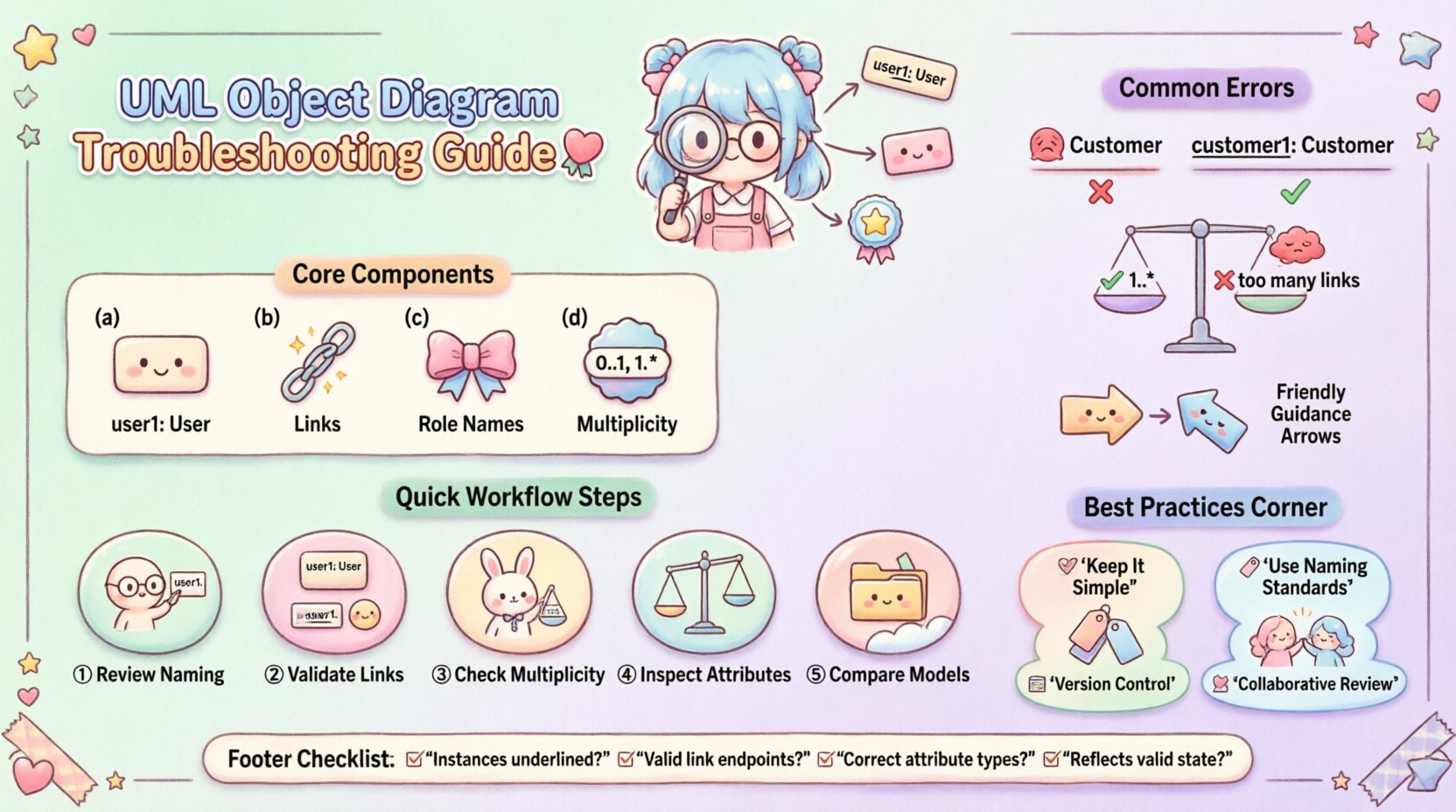
🔍 Understanding Object Diagram Structure
Before troubleshooting, it is essential to understand the core components. An object diagram consists of:
- Instances: Represented as rectangles with underlined class names (e.g.,
user1: User). - Links: Lines connecting instances, representing associations.
- Role Names: Labels on links indicating the role an instance plays in the relationship.
- Multiplicity: Numbers indicating how many instances can participate in a link (e.g.,
0..1,1..*).
Errors often arise when these elements conflict with the underlying class definitions or when they fail to represent a valid system state.
⚠️ Common Syntax and Naming Errors
Syntactic validity is the first line of defense. If the diagram does not adhere to standard notation rules, it cannot be processed correctly by modeling engines or interpreted by developers.
1. Instance Naming Conventions
Instances must follow a specific naming pattern to distinguish them from classes. The standard format is instanceName: ClassName.
- Incorrect: A rectangle labeled only with a class name without an instance prefix.
- Incorrect: Using the class name as the instance name without the colon separator.
- Correct:
customer1: Customerororder_5: Order.
When troubleshooting, check every object rectangle. Ensure the instance name is unique within the diagram scope and distinct from the class name.
2. Visibility Modifiers
Attributes and methods within instances should generally be hidden in object diagrams unless they are critical to the specific state being shown. However, when displayed, they must follow visibility rules.
- Public: Denoted by
+. - Private: Denoted by
-. - Protected: Denoted by
#.
If an attribute is shown in an object diagram, it must have a valid value assigned. An attribute displayed without a value is technically incomplete for an object instance.
🔗 Relationship and Link Troubleshooting
Links represent the dynamic connections between objects. Errors here are often more subtle than naming issues and can lead to significant logical flaws in the design.
1. Link Directionality
Links must match the navigability defined in the class diagram. If a link is directed, it implies one instance knows about the other.
- Check: Ensure arrowheads point in the correct direction based on the association definition.
- Check: Verify that multiplicity is consistent with the direction of the link.
2. Multiplicity Violations
Multiplicity defines the cardinality of relationships. This is the most frequent source of errors in object diagrams.
| Common Error | Description | Correction Strategy |
|---|---|---|
| Over-association | Too many links for a defined maximum multiplicity | Remove excess links or adjust multiplicity in the class model |
| Under-association | Missing required links for a minimum multiplicity | Add necessary links to meet the minimum count |
| Invalid Multiplicity | Using values like 0..0 or non-integer ranges |
Use standard ranges like 0..1, 1..*, or specific integers |
3. Role Names and Aggregation
Role names clarify how objects participate in associations. Confusion often arises between Aggregation and Composition.
- Aggregation: A weak relationship (whole-part). The part can exist without the whole. Represented by an open diamond.
- Composition: A strong relationship. The part cannot exist without the whole. Represented by a filled diamond.
If an object diagram shows a composition link, deleting the “whole” object should logically imply the “part” object is also removed. If the diagram suggests otherwise, the relationship type is likely incorrect.
🧩 Instance and Attribute Display Issues
Object diagrams often attempt to show data values. However, cluttering a diagram with too much information reduces readability.
1. Attribute Value Formatting
Values must be clearly distinguished from attribute names. The standard notation places a colon after the attribute name, followed by the value.
- Format:
attributeName: value - Example:
status: active,age: 30
If values are missing for required fields, the instance state is undefined. This is a common issue when diagrams are used for data validation scenarios.
2. Type Consistency
Ensure the data types of attribute values match the class definition. A string value cannot be assigned to an integer attribute.
- Check: Verify that numerical values are not quoted as strings unless the attribute type is explicitly text.
- Check: Ensure boolean values are represented as
trueorfalse, not1or0.
🔄 Consistency with Class Diagrams
An object diagram is a derivative of the class diagram. It cannot exist in a vacuum. Discrepancies between the two models are a primary source of confusion.
1. Class Existence
Every instance in an object diagram must correspond to a defined class in the class diagram. If an instance references a class that does not exist in the model, the diagram is invalid.
2. Association Definition
Links in the object diagram must be defined in the class diagram. You cannot introduce a new relationship type in the object diagram that was not specified in the class structure.
3. Inheritance and Polymorphism
If a class inherits from another, instances must reflect this hierarchy correctly. An instance of a subclass can be linked where the superclass is expected, but the instance label should reflect the actual class.
🛠️ Troubleshooting Workflow
Follow this systematic approach to validate your diagrams.
- Review Naming: Check all instance labels for the
name: Classformat. - Validate Links: Ensure every link connects two valid instances and matches a defined association.
- Check Multiplicity: Count the links at each end of an association to ensure they fall within the defined range.
- Inspect Attributes: Verify that displayed attributes have values and correct data types.
- Compare Models: Cross-reference with the class diagram to ensure structural alignment.
📋 Common Errors Checklist
Use this checklist during your review process to catch recurring issues.
- ☐ Are all instances underlined?
- ☐ Do all links have valid endpoints?
- ☐ Are role names present where necessary?
- ☐ Is multiplicity consistent across all links?
- ☐ Are attribute values typed correctly?
- ☐ Are there orphaned links (one end unconnected)?
- ☐ Does the diagram reflect a valid system state?
- ☐ Are inheritance relationships clearly marked?
🛡️ Best Practices for Diagram Integrity
Maintaining high-quality diagrams requires discipline. Adhering to these practices reduces the need for troubleshooting later.
1. Keep It Simple
Do not attempt to show every attribute for every instance. Focus on the data relevant to the specific scenario you are illustrating. Excessive detail obscures the relationships.
2. Use Naming Standards
Establish a naming convention for instances early. Using prefixes like obj_ or inst_ can help distinguish instances from classes quickly.
3. Version Control
Since object diagrams represent snapshots, keep track of different states. If the system evolves, the object diagram must be updated to reflect new instances and removed ones.
4. Collaborative Review
Have peers review the diagram. A fresh pair of eyes can spot logical inconsistencies that the creator might miss, such as a link that implies a relationship impossible in the business logic.
🧪 Advanced Validation Techniques
For complex systems, manual validation is insufficient. Consider the following advanced checks.
1. Path Tracing
Select an instance and trace all possible paths through the links. Ensure that no dead ends occur where a link is defined but not implemented in the diagram. This is crucial for navigation logic.
2. State Consistency
If multiple object diagrams are created for different states, ensure that common instances are labeled consistently. Changing an instance name between diagrams without a corresponding update in the model creates confusion.
3. Constraint Verification
Check if any constraints defined in the class diagram (e.g., OCL expressions) are violated in the object diagram. For example, if a constraint states that a user must have at least one email address, the object diagram must reflect this.
🚀 Moving Forward
Creating valid UML object diagrams requires attention to detail and a deep understanding of the underlying class structure. By systematically addressing naming, linking, and multiplicity issues, you ensure that your diagrams serve their purpose: accurately representing the system’s state.
Remember that these diagrams are living documents. As the system evolves, the diagrams must evolve with it. Regular reviews and adherence to the troubleshooting steps outlined here will maintain the integrity of your design artifacts.
Focus on clarity and accuracy. A well-constructed object diagram is a valuable tool for communication between developers, architects, and stakeholders. It bridges the gap between abstract class designs and concrete system behavior.