


In the evolving landscape of software engineering, visual representation remains a cornerstone of clarity. Among the various modeling techniques available, the UML Object Diagram occupies a unique position. It captures a snapshot of instances at a specific moment in time, offering a view into the runtime state of a system. While often overshadowed by Class Diagrams, the Object Diagram serves a critical function in understanding complex data relationships and state configurations. As architectures shift towards distributed systems and cloud-native environments, the role of static modeling is undergoing a significant transformation.
This guide explores the trajectory of Object Diagrams, how they integrate with modern development practices, and what lies ahead for static structure modeling. We will examine the theoretical underpinnings, practical applications, and the challenges inherent in maintaining these models alongside rapidly changing codebases.
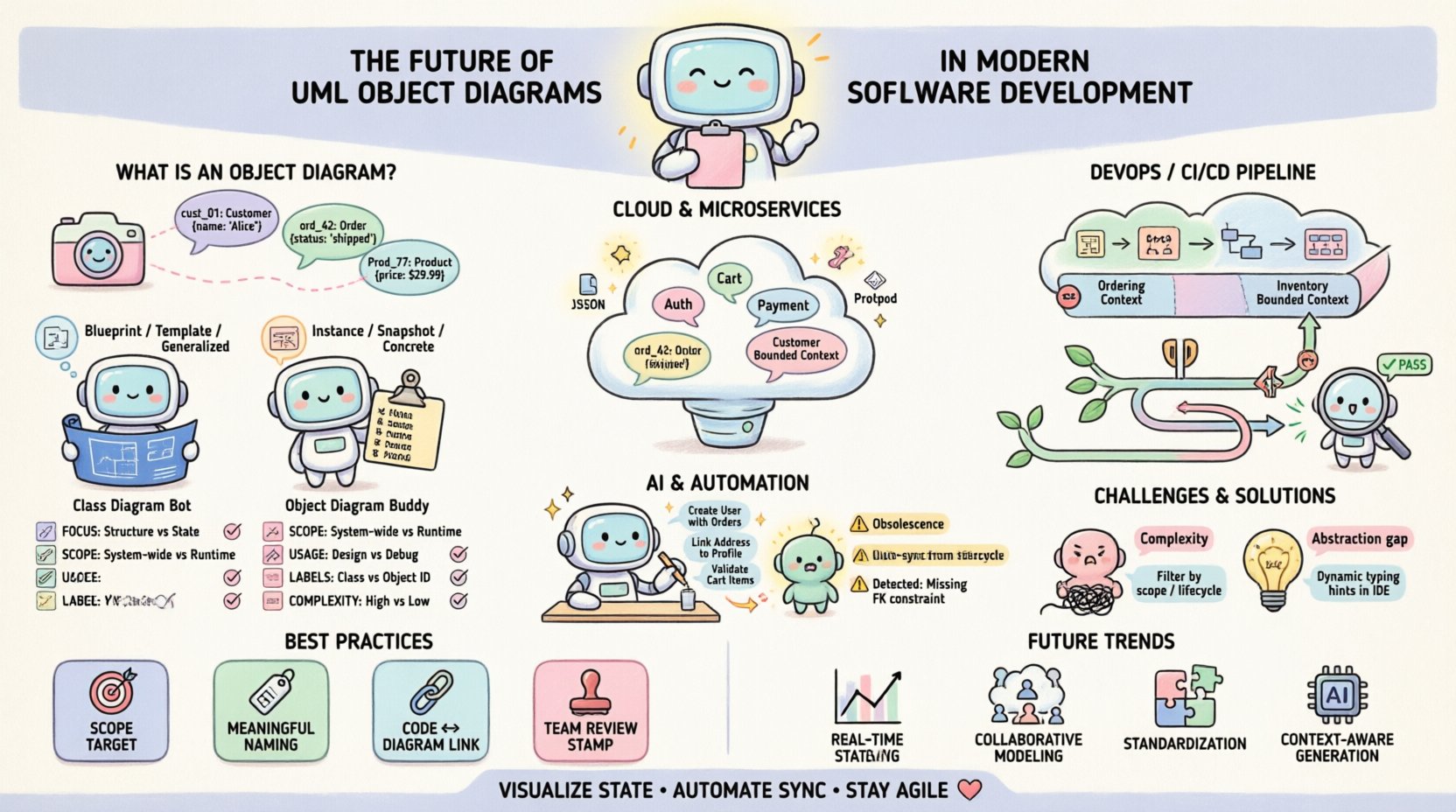
🔍 Understanding the Core: What is an Object Diagram?
An Object Diagram represents a specific instance of a system. Unlike a Class Diagram, which defines the blueprint or template, an Object Diagram depicts the actual objects populated with data. It is essentially a snapshot of the memory state of a running program, visualized for human comprehension.
- Instances over Types: While classes define properties and methods, objects define specific values for those properties.
- Static Structure: It shows relationships (associations) between instances, not the behavior (methods) they execute.
- Time-Bound: A valid representation of a system at a particular point in execution.
In modern development, this distinction is vital. When debugging a race condition or analyzing a memory leak, understanding the specific object graph is often more useful than understanding the abstract class hierarchy. Object Diagrams allow architects to visualize the connectivity of data entities without the noise of behavioral logic.
⚖️ Object Diagrams vs. Class Diagrams: A Critical Comparison
Confusion often arises between these two modeling artifacts. To clarify their distinct purposes, consider the following breakdown. This comparison helps determine when to utilize each model during the design phase.
| Feature | Class Diagram | Object Diagram |
|---|---|---|
| Focus | Blueprints and Templates | Instances and Data |
| Scope | Static Structure (Generic) | Static Structure (Specific) |
| Usage | Design Phase, Code Generation | Debugging, Documentation, Testing |
| Labels | Class Names (e.g., Customer) |
Object Names (e.g., cust_01) |
| Complexity | High-level logic | Low-level state detail |
While Class Diagrams define the rules of engagement for data, Object Diagrams show the current players on the field. In a large-scale application, a Class Diagram might span hundreds of pages, making it difficult to grasp specific interactions. An Object Diagram narrows the focus to a single scenario, such as a checkout process or a user session, making the data flow tangible.
🏗️ Object Diagrams in Microservices and Cloud Architecture
The shift from monolithic applications to microservices has changed how we view data structure. In a monolith, all objects reside in the same process space. In a distributed environment, objects are serialized and transmitted across network boundaries. This reality impacts how Object Diagrams are constructed and maintained.
1. Serialization and Persistence
When services communicate, they do so via JSON, XML, or Protobuf. The Object Diagram serves as the source of truth for what these serialized payloads look like. It defines the schema constraints that must be upheld during transmission.
- Schema Validation: Diagrams help define the strict boundaries of data exchange.
- State Management: In event-driven architectures, the state of an aggregate root is often persisted. Object Diagrams visualize this aggregate.
- Latency Considerations: Understanding object relationships helps identify N+1 query problems in data fetching.
2. Domain-Driven Design (DDD)
DDD relies heavily on bounded contexts. Object Diagrams are instrumental in defining the scope of these contexts. By mapping specific instances to a bounded context, teams can ensure that cross-context dependencies are minimized and intentional.
For example, a Order object in the Sales context might reference a Customer object. An Object Diagram clarifies whether this reference is a direct pointer or a surrogate key. This distinction is critical for performance optimization in high-throughput systems.
🔄 Integration with DevOps and CI/CD Pipelines
Traditionally, modeling was a separate phase before coding began. In modern DevOps environments, the line between design and deployment is blurred. Object Diagrams must evolve to support continuous integration.
1. Automated Documentation
One of the primary challenges with Object Diagrams is obsolescence. As code changes, diagrams become outdated. To mitigate this, modeling tools must integrate with version control systems.
- Code-to-Model Synchronization: Tools can parse source code to update diagrams automatically.
- Commit Hooks: Diagrams can be regenerated as part of the build process to ensure consistency.
- Visual Regression: Changes in object graphs can be flagged as alerts during deployment.
2. Testing and Quality Assurance
Testers often struggle to understand the expected state of an application after a specific action. Object Diagrams provide a visual contract for test cases.
- Unit Testing: Verify that a method creates the expected object instances.
- Integration Testing: Validate the connectivity between service endpoints based on the defined object graph.
- Debugging: When a test fails, comparing the actual runtime graph against the diagram highlights discrepancies immediately.
🤖 The Role of AI and Automation
Artificial Intelligence is poised to change how we interact with static models. Large Language Models (LLMs) can interpret natural language requirements and generate corresponding Object Diagrams.
1. Generative Modeling
Instead of manually drawing boxes and lines, developers can describe the data structure. An AI agent can generate the diagram, ensuring adherence to UML standards and consistency with existing Class Diagrams.
- Natural Language Input: “Create a diagram showing a User with multiple Orders.”
- Context Awareness: The AI understands inheritance and polymorphism constraints.
- Correction: AI can detect circular references or orphaned objects that human designers might miss.
2. Predictive Analysis
Advanced modeling tools may use historical data to predict object lifecycle issues. By analyzing the frequency of object creation and destruction, the system can suggest optimizations for memory management.
This shifts the diagram from a passive document to an active analytical tool. It moves beyond “what does this look like?” to “how does this behave under load?”.
⚠️ Challenges in Maintenance and Relevance
Despite their utility, Object Diagrams face significant hurdles in modern agile environments. The speed of iteration often outpaces the ability to document.
1. The Obsolescence Problem
A diagram created today may be invalid by next sprint. If the model is not updated automatically, it becomes technical debt. Teams often abandon modeling because the cost of maintenance exceeds the benefit.
- Solution: Treat diagrams as code. Store them in the repository.
- Solution: Link diagrams directly to unit tests to enforce updates.
2. Abstraction vs. Reality
There is a risk of modeling the ideal state rather than the actual state. In highly dynamic languages, objects can change structure at runtime. A static diagram cannot capture this fluidity.
- Dynamic Typing: In languages like Python or JavaScript, object attributes are not strictly defined.
- Reflection: Programs that inspect their own structure render static diagrams less accurate.
3. Cognitive Load
Complex systems produce complex graphs. An Object Diagram with hundreds of instances can be unreadable. It is essential to filter the view to show only relevant relationships for the specific use case.
- Filtering: Focus on specific object types rather than showing the entire graph.
- Annotations: Use labels to explain the significance of specific links.
🛠️ Best Practices for Implementation
To ensure Object Diagrams remain valuable assets, teams should adhere to a set of rigorous standards.
1. Define Scope Clearly
Never attempt to diagram an entire system in one view. Break down the system into subsystems or modules. Each diagram should tell a specific story about a specific domain.
- Use Cases: Create a diagram for each major user story.
- Context: Define the boundaries of the diagram explicitly.
2. Consistency in Naming
Object names should be unique and descriptive. Avoid generic names like obj1 or data. Use identifiers that reflect the business entity, such as invoice_1024 or active_session.
- Format: Adopt a naming convention (e.g., camelCase or snake_case).
- Clarity: Names should be understandable without consulting the code.
3. Link to Code
Diagram tools should support hyperlinks to source code. When a developer clicks an object in the diagram, they should be able to navigate to the class definition or the instance creation site.
- Traceability: Ensures the diagram reflects the actual codebase.
- Efficiency: Reduces the time spent searching for implementation details.
4. Regular Reviews
Incorporate diagram reviews into the code review process. If the code changes the object structure, the diagram must change. This ensures the documentation stays synchronized with the product.
- Checklist: Is the diagram updated in this pull request?
- Feedback: Are the relationships accurately depicted?
🔮 Future Trends and Outlook
As we look further ahead, the integration of modeling with runtime environments will deepen. We are moving towards a paradigm where the diagram is not just a document, but a live interface.
- Real-Time Visualization: Diagrams that update as the application runs, showing live data flow.
- Interactive Debugging: Clicking an object in the diagram to execute methods or inspect memory.
- Collaborative Modeling: Cloud-based platforms allowing multiple architects to edit the graph simultaneously.
- Standardization: Wider adoption of open standards for model interchange, ensuring tools can communicate regardless of vendor.
📉 Common Pitfalls to Avoid
Even with best practices, teams often stumble. Being aware of common mistakes can save significant time.
- Over-Modeling: Creating diagrams for simple features that do not require visualization.
- Under-Modeling: Skipping diagrams for complex logic that requires structural clarity.
- Ignoring Relationships: Focusing on objects but neglecting the links between them, which often hold the critical business logic.
- Static Mindset: Treating the diagram as a one-time deliverable rather than a living artifact.
🔧 Technical Implementation Details
For teams implementing these diagrams, technical considerations regarding storage and rendering are essential.
1. File Formats
Standard formats like XMI (XML Metadata Interchange) allow for portability between different modeling environments. Using open formats ensures long-term accessibility of the models.
- Interoperability: Avoid proprietary formats that lock data into a single vendor.
- Version Control: Text-based formats are easier to diff and merge in Git.
2. Rendering Performance
Large diagrams can cause rendering lag in web-based viewers. Techniques such as lazy loading and node clustering help maintain performance.
- Optimization: Only render visible nodes during zooming.
- Scalability: Use canvas-based rendering instead of DOM elements for large graphs.
🌐 Global Standards and Compliance
In regulated industries, documentation is not optional. Object Diagrams often serve as evidence for compliance audits.
- Traceability: Demonstrating how data flows through the system for security reviews.
- Validation: Proving that the system adheres to data protection regulations.
- Archiving: Maintaining historical versions of diagrams for legal requirements.
The rigor required for compliance often forces teams to maintain higher quality models than they would otherwise. This necessity drives the adoption of better modeling practices across the industry.
📝 Final Thoughts on Modeling Evolution
The utility of UML Object Diagrams lies in their ability to ground abstract concepts in concrete reality. They bridge the gap between the theoretical class structure and the messy, dynamic nature of running software. While the tools and technologies surrounding them change, the fundamental need to visualize state remains constant.
Success depends on balancing detail with maintenance effort. Teams that treat diagrams as living documents, integrated into the development workflow, will find them to be powerful tools for communication and quality assurance. Those that treat them as static artifacts will find them burdensome. The future belongs to those who can automate the synchronization between code and model, ensuring that the visualization is always a true reflection of the system.
By adhering to best practices, leveraging automation, and focusing on clarity, Object Diagrams will continue to play a vital role in the architecture of robust, scalable, and maintainable software systems.