


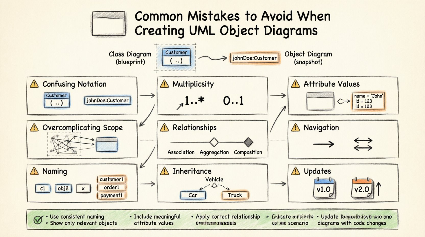
UML Object Diagrams serve as critical snapshots of a system at a specific moment in time. Unlike Class Diagrams, which define the blueprint, Object Diagrams visualize actual instances and their relationships. They provide clarity on how data flows and how objects interact within a concrete scenario. However, creating these diagrams requires precision. Small errors can lead to significant misunderstandings during implementation.
This guide explores the frequent pitfalls encountered when modeling object instances. We will examine structural inconsistencies, relationship errors, and naming conventions. By understanding these common mistakes, you can ensure your diagrams remain accurate, maintainable, and useful for stakeholders. Let us dive into the specifics of UML instance modeling.
Understanding the Purpose of Object Diagrams 📐
Before identifying mistakes, it is essential to define what an Object Diagram represents. It is a static snapshot of the system state. It shows:
- Instances of classes (objects).
- Links between instances (associations).
- Attribute values for specific instances.
- Multiplicity constraints as they apply to those specific instances.
When the purpose is blurred, the diagram loses its value. Many errors stem from confusing the static structure (Class Diagram) with the dynamic state (Object Diagram). Keeping the distinction clear is the first step toward accuracy.
Mistake 1: Confusing Class and Object Notation 🔄
One of the most prevalent errors is mixing notations. A Class Diagram uses bold headers for class names and lists attributes and methods. An Object Diagram must differentiate instances from types.
The Error
Using the class name alone for an instance box. In an Object Diagram, an instance should be named using the format instanceName : ClassName.
The Consequence
If you label a box simply as Customer, it looks like a class definition. Readers cannot distinguish between the type definition and the actual data. This leads to ambiguity during code generation or database schema design.
The Correction
Always use the colon syntax. For example, customer1 : Customer or order45 : Order. This visually signals that this box represents a specific entity existing in memory, not a general template.
Visual Comparison
| Incorrect Notation | Correct Notation | Why It Matters |
|---|---|---|
Customer |
johnDoe : Customer |
Clarifies instance vs. type |
BankAccount |
acc123 : BankAccount |
Prevents confusion with class structure |
Mistake 2: Ignoring Multiplicity Constraints 📉
Multiplicity defines how many instances of one class relate to another. In an Object Diagram, you are looking at a specific scenario. Often, creators draw lines without adhering to the cardinality rules defined in the Class Diagram.
The Error
Creating a link between two objects that violates the defined multiplicity. For example, if a Department can have 0..* Employees, but your diagram shows a single Department linked to three Employees without any indication of a collection, it implies a 1:1 relationship incorrectly.
The Technical Impact
Developers rely on these diagrams to understand data constraints. If the diagram suggests a one-to-one relationship where a one-to-many exists, the database schema might be normalized incorrectly. This can lead to data duplication or referential integrity errors.
Best Practice
- Ensure the number of links matches the multiplicity range defined in the class model.
- Use collections or arrays in the object notation if multiple instances are linked to one.
- Label the link ends with the actual multiplicity observed in the snapshot.
Mistake 3: Inconsistent Attribute Values 📝
Object Diagrams are unique because they show actual values. However, many creators omit values entirely or use placeholders like null or empty inconsistently.
The Error
Leaving attributes blank when they are critical to the state. For instance, an Order object with no status or totalAmount defined is incomplete. Alternatively, using generic values like test123 for all instances reduces clarity.
The Correction
Populate attributes with realistic data that reflects the scenario. If an order is pending, state status = pending. If an account is inactive, set isActive = false. This helps stakeholders validate the logic.
When to Omit Values
Not every attribute needs a value in every diagram. Focus on the attributes relevant to the scenario being modeled. If the diagram is about navigation, focus on links. If it is about validation, focus on state flags.
Mistake 4: Overcomplicating the Scope 🌐
A common issue is trying to model the entire system in a single Object Diagram. These diagrams are snapshots. A single diagram should focus on a specific use case or a specific slice of the data model.
The Error
Drawing thousands of objects to represent the whole database. This creates a cluttered visual that is impossible to read. It defeats the purpose of abstraction.
The Consequence
Readers cannot identify the relationships of interest. The diagram becomes a wall of text and boxes. Maintenance becomes a nightmare because updating one small part requires redrawing the whole mess.
Strategy for Scope
- Focus on Use Cases: Create one diagram for a login flow, another for a checkout flow.
- Limit Object Count: Keep the number of instances manageable (e.g., 5 to 15 objects).
- Group Related Objects: Use framing or compartments to group related instances.
Mistake 5: Misrepresenting Associations and Aggregations 🔗
Relationships between objects must be represented correctly. There is a difference between a simple association, an aggregation, and a composition. Errors here confuse ownership and lifecycle.
The Error
Using a simple line for a composition relationship. In an Object Diagram, a composition implies that the child object cannot exist without the parent. A simple line suggests a loose coupling.
Visual Distinctions
| Relationship Type | Visual Symbol | Implication |
|---|---|---|
| Association | Simple Line | Loose connection, independent lifecycles. |
| Aggregation | Hollow Diamond | Whole-part relationship, parts can exist independently. |
| Composition | Filled Diamond | Strong ownership, parts die with the whole. |
Common Pitfall
Using a filled diamond for an association that is actually optional. If the relationship is optional, a filled diamond is misleading. It suggests mandatory ownership. Always verify the lifecycle rules before applying the diamond symbol.
Mistake 6: Neglecting Navigation Paths 🧭
Object Diagrams are often used to understand how a programmer navigates the object graph. If the arrows or link labels do not indicate direction, the diagram is less useful for coding.
The Error
Using bidirectional lines when the code only allows one-way access. For example, a Driver knows a Car, but the Car does not store a reference back to the Driver. If you draw a line with diamonds on both ends, you imply two-way access.
The Fix
- Use arrows to indicate navigation direction.
- Label the link with the role name if necessary.
- Ensure the direction matches the getter/setter implementation in the code.
Mistake 7: Inconsistent Naming Conventions 🏷️
Naming is a critical part of documentation. Inconsistent naming makes the diagram hard to scan and reference.
The Error
Using obj1, tempVar, User123, and customer_instance in the same diagram. This creates cognitive load. Readers spend time deciphering names rather than understanding relationships.
Recommended Convention
- Use descriptive names based on the role in the scenario.
- Prefix with the class name if the role is generic (e.g.,
primaryUser). - Avoid generic numbers unless they represent a specific ID (e.g.,
order_554). - Keep naming consistent across all diagrams in the project.
Mistake 8: Ignoring Inheritance in Object Diagrams 🏛️
While Object Diagrams focus on instances, inheritance still plays a role. If a class is a subclass of another, the instance should reflect that type explicitly.
The Error
Lumping all instances into their parent class type. If you have a Vehicle class and Car and Truck subclasses, an instance should be labeled as myCar : Car, not myCar : Vehicle.
Why It Matters
Subclasses often have different attributes or behaviors. Labeling an instance as the parent class hides the specific properties of the subclass. This can lead to type errors if the code relies on subclass-specific methods.
Mistake 9: Failing to Update with System Changes 🔄
Object Diagrams represent a state. Systems evolve. A diagram created today may be obsolete tomorrow. The mistake is treating the diagram as a static artifact that never changes.
The Risk
Developers follow the old diagram and implement the old logic. This creates technical debt. The documentation diverges from the code.
Maintenance Strategy
- Review diagrams during sprint retrospectives.
- Update diagrams when a major feature changes the data model.
- Version the diagrams if the system has multiple active configurations.
Deep Dive: The Relationship Between Class and Object Diagrams 🔍
It is vital to understand how these two diagrams interact. The Class Diagram is the contract. The Object Diagram is the execution.
Key Differences
- Class Diagram: Defines structure, methods, attributes, and relationships generally. It is timeless.
- Object Diagram: Defines a specific set of instances and their current values. It is temporal.
Validation Process
Before finalizing an Object Diagram, validate it against the Class Diagram. Ask the following questions:
- Does every object in the diagram have a corresponding class?
- Do all links in the diagram exist in the Class Diagram?
- Are the attribute types consistent with the class definitions?
- Do the multiplicity constraints match?
Advanced Consideration: Serialization and Persistence 🗄️
When designing systems that store state (databases, file systems), Object Diagrams help visualize the serialization process. A common mistake is ignoring how objects are stored.
The Error
Modeling objects in memory without considering how they map to storage. For example, a graph of objects might be circular. In a database, circular references can cause issues if not handled correctly.
The Correction
Analyze the Object Diagram for cycles. If you see A linked to B and B linked back to A, consider how this is persisted. This might require breaking the link in storage or using foreign keys carefully.
Summary of Best Practices ✅
To ensure high-quality UML Object Diagrams, adhere to these core principles:
- Use Instance Syntax: Always label boxes as
name : Type. - Respect Multiplicity: Ensure link counts match cardinality rules.
- Define Scope: Focus on specific scenarios, not the entire database.
- Label Relationships: Use arrows and role names to show navigation.
- Populate Values: Show realistic attribute data where relevant.
- Maintain Consistency: Use consistent naming across all diagrams.
- Validate Against Classes: Ensure every instance maps to a valid class definition.
Common Questions Regarding Object Diagrams ❓
Can I use Object Diagrams for Dynamic Behavior?
No. Object Diagrams are static. They show state, not behavior. For behavior, use Sequence Diagrams or Activity Diagrams. Using Object Diagrams to show flow confuses the reader.
Are Object Diagrams Mandatory in Every Project?
Not always. For simple projects, they might be redundant. However, for complex systems with intricate data relationships, they are invaluable for debugging and understanding state.
How Do I Handle Collections in Object Diagrams?
You can represent a collection by drawing multiple lines to the same object or using a list notation inside the object box (e.g., orders: List<Order>). Be explicit about whether the object holds a reference to a collection or individual instances.
Final Thoughts on Diagram Accuracy 🎯
Accuracy in modeling is not about perfection; it is about communication. A diagram that is slightly simplified but accurate is better than a complex diagram that is confusing. Avoid the mistakes outlined above to ensure your diagrams serve their purpose: clarifying the system for developers and stakeholders.
By focusing on notation, scope, and relationships, you create diagrams that stand the test of time. They become living documents that guide the development process rather than obstacles. Keep your diagrams clean, consistent, and focused on the specific state you intend to convey.