


Mastering the complex interactions within your software system starts with clear visualization. The PlantUML Sequence Diagram Builder by Visual Paradigm is a powerful, web-based tool designed to simplify this process. This article provides a deep dive into how this tool enables you to create professional, interactive sequence diagrams for dynamic system behaviors. We’ll explore its core features, demonstrate a real-world example, and show you how to leverage its intuitive interface to document complex user interactions. The goal is to transform your understanding of system dynamics into a clear, visual narrative.
Quick Summary: Key Benefits of the PlantUML Sequence Diagram Builder
-
Intuitive Workflow: Define participants and messages using simple forms, not complex code.
-
Real-time Feedback: See your diagram render instantly as you build, with live code generation.
-
Advanced Control: Model complex scenarios with alt, opt, and loop fragments for conditional logic.
-
Local & Secure: Save and load your projects as JSON files directly to your computer.
-
Professional Output: Generate clear diagrams for documentation, presentations, and team collaboration.
Understanding the Power of Sequence Diagrams
Sequence diagrams are a cornerstone of UML (Unified Modeling Language) used to illustrate the dynamic behavior of a system. They show how different objects or components interact over time to accomplish a specific task. This is crucial for software architects, engineers, and business analysts to ensure everyone understands the flow of messages and control. The challenge lies in creating these diagrams efficiently. The PlantUML Sequence Diagram Builder tackles this by providing a structured, form-based interface that removes the friction of manual syntax writing. Instead of wrestling with PlantUML code, you focus on the logic of the interaction, and the tool handles the technical rendering.
Feature Deep Dive: How the Builder Works
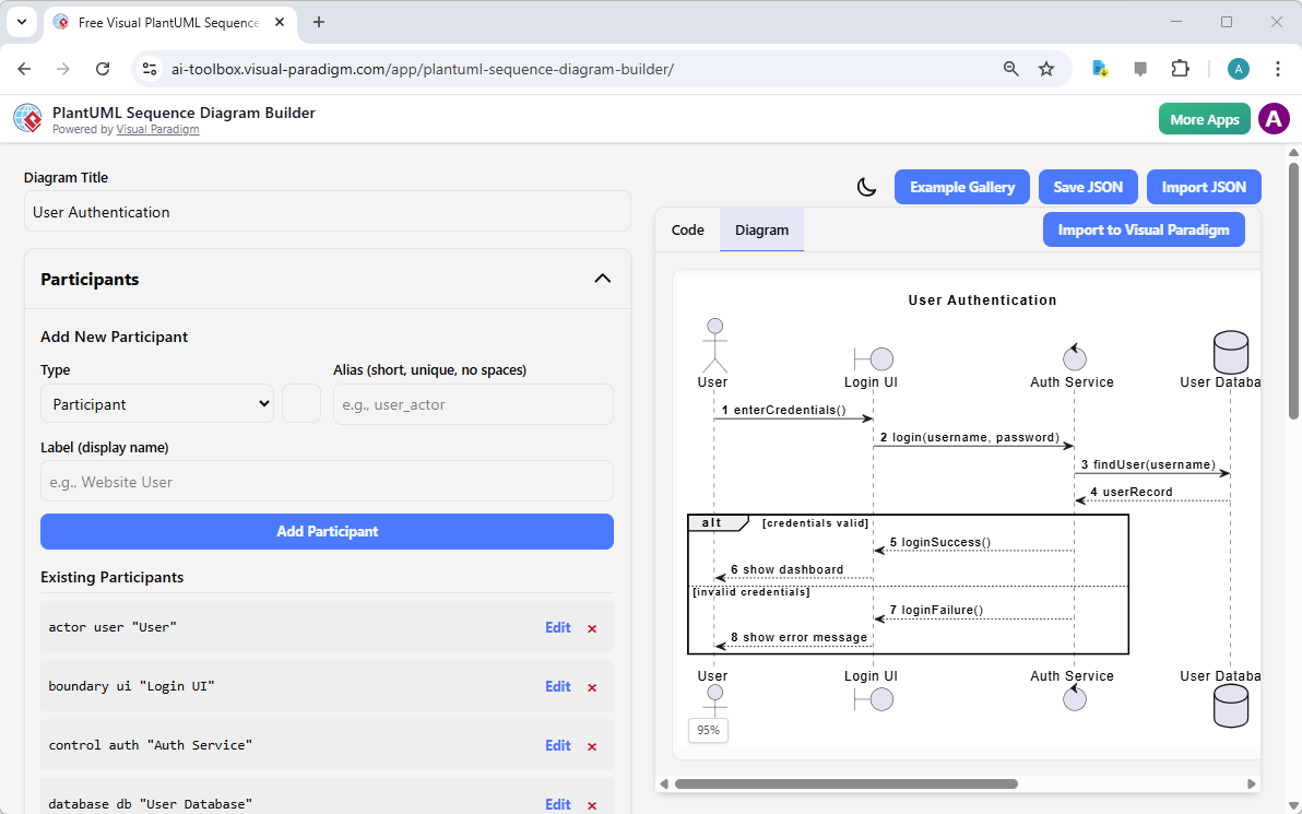
Let’s break down the core functionality of the PlantUML Sequence Diagram Builder, using the provided screenshot as our guide. The interface is cleanly divided into a left-hand panel for defining the diagram’s structure and a right-hand panel for visualizing the result.
Structured Participant Editor
On the left, the Participants section allows you to define every entity involved in the interaction. You can add different types of participants, such as actors (like the “User”), boundaries (like “Login UI”), controls (like “Auth Service”), and databases (like “User Database”). Each participant has a unique Alias (e.g., “user”, “Login UI”) and a Label (e.g., “Website User”) for the visual diagram. This structured approach ensures a clear and consistent definition of all system components before you model their interactions.
Structured Sequence Editor
The Sequence section is where the dynamic behavior unfolds. You add sequence steps, including messages (e.g., “enterCredentials()”), notes, and control flow fragments. The example in the screenshot demonstrates a powerful feature: the alt fragment. This allows you to model alternative paths in a process, such as the “credentials valid” path leading to a successful login and the “invalid credentials” path leading to an error message. This is essential for accurately capturing real-world system logic where decisions are made based on data.
Live Code and Visual Preview
The heart of the tool is its real-time feedback loop. As you define participants and sequence steps, the Live PlantUML Code Generation section updates instantly, showing the corresponding code. This transparency is invaluable for learning and debugging. Simultaneously, the Live Visual Diagram Preview on the right renders the diagram in real-time. This means you can see the impact of your changes immediately, ensuring your diagram is accurate and visually clear. The screenshot shows a complete “User Authentication” flow, with messages like “login(username, password)” and “loginSuccess()”, all rendered in a clean, professional style.
Project Management and Sharing
Once you’ve built your diagram, the tool provides robust project management. The Save JSON and Import JSON buttons allow you to securely save your work locally on your computer. This ensures your valuable design data is under your control and can be loaded back into the tool for further refinement. While there’s no direct sharing feature, you can export the visual diagram as an image or use the generated PlantUML code in other applications.
Applying the Tool: A Real-World Example
Let’s see the PlantUML Sequence Diagram Builder in action with a practical scenario. The provided screenshot shows a “User Authentication” diagram. Here’s how you would create it:
-
Set the Title: Enter “User Authentication” in the “Diagram Title” field.
-
Add Participants: Use the “Add New Participant” form to create: an actor “User”, a boundary “Login UI”, a control “Auth Service”, and a database “User Database”.
-
Build the Sequence: Start adding messages. For example, add a message from “User” to “Login UI” with the label “enterCredentials()”. Then add a message from “Login UI” to “Auth Service” with “login(username, password)”.
-
Model Conditional Logic: Use the “Add Alt” button to create an alternative path. In the “alt” block, add a message for “loginSuccess()” and another for “loginFailure()”.
-
Save and Export: Click “Save JSON” to store your project locally. Then, export the visual diagram as an image for your documentation.
This process is fast, intuitive, and eliminates the guesswork of writing PlantUML code manually.
Conclusion: Visualize Your System’s Behavior with Confidence
The PlantUML Sequence Diagram Builder is a game-changer for anyone who needs to document and understand complex system interactions. By providing a structured, form-based interface with real-time code and visual feedback, it removes the barriers to creating professional sequence diagrams. Whether you’re a software architect designing a new feature, a business analyst documenting a process, or a student learning UML, this tool empowers you to visualize your system’s dynamic behavior clearly and efficiently. It transforms the abstract concept of a “user login flow” into a concrete, visual narrative.
Ready to bring your system’s interactions to life? Try the PlantUML Sequence Diagram Builder now and see how easy it is to create professional, interactive diagrams in minutes.
Related Links
Sequence diagrams are a primary type of interaction diagram used to visualize the timing and order of messages exchanged between objects during specific software scenarios.
-
Comprehensive Guide to Sequence Diagrams in Software Design: This foundational resource covers the essential structure and purpose of modeling dynamic system behavior and interaction sequences.
-
AI-Powered Sequence Diagram Refinement Tool: Discover how to use artificial intelligence to improve diagram readability, structural correctness, and consistency automatically.
-
How to Model MVC with UML Sequence Diagram: This guide provides a detailed walkthrough on visualizing the interactions between Model, View, and Controller components within an architecture.
-
Animating Sequence Diagrams in Visual Paradigm: This tutorial demonstrates how to animate software workflows, providing a dynamic way to communicate system interactions to stakeholders.
-
PlantUML Sequence Diagram Generator: Use a visual builder tool to rapidly generate professional UML diagrams using PlantUML syntax and an intuitive participant wizard.
-
User Guide: Sequence Diagrams in Visual Paradigm: A comprehensive technical manual that outlines the full workflow for creating, editing, and exporting sequence models.
-
Visual Paradigm Gallery: Sequence Diagram Examples: A curated collection of real-world examples intended to provide design inspiration and guidance for complex interaction modeling.
-
Mastering Sequence Diagrams with AI Chatbot Tutorial: A practical case study focused on building diagrams for an e-commerce system through natural language interaction with an AI assistant.
-
Mastering Use Case Elaboration with Sequence Diagrams: Learn how to refine use cases by mapping flow-of-events to detailed message sequences for precise requirement validation.
-
Separate Sequence Diagrams for Main and Exceptional Flows: This article explores advanced techniques for improving model clarity by separating standard success paths from complex error-handling and exceptional flows.